
Manual


1. Be careful when installing fillerplate assembly not to damage wires.
2. See "EM ELECTRICAL OPTIONS" before reinstalling filler plate.
CYLINDER INSTALLATION
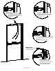
Cut fillerplate & extrusion to
desired length
during cutting
Protect wires
2
tape
with
Secure
FLUSH to extrusion
prior to cutting
Align fillerplate
1
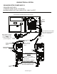
View A
Modular Cable
Connection
View B
12 Pin Connection
(note: board layout may differ slightly from layout shown)
Remove endcap, endcap bracket & fillerplate subassembly.
Disconnect cable assembly (view A),
12 pin connector (view B), and battery
Do not overtighten
NOTE:
CAUTION:
Tighten with hand tools only.
See View A & B above
Re-connect in the following order:
1) Cable assembly (view A),
2) Battery,
3) 12 pin connector (view B),
Install fillerplate subassembly
& endcap bracket.
Install mortise cylinder
with hex nut provided
INSTALLING MORTISE CYLINDER
Dogging lever should be in "ON"
(CCW) position before sliding back
into extrusion
Use optional cylinder collar
(Detex p/n: ECL-1595)
when
installing 7-pin mortise cylinder
2
(1) Move placement of
spacers to match length
of cylinder used to allow
smooth rotation of cam.
2) All cylinder spacers
must be used, either
on top or bottom
RE-INSTALL FILLERPLATE
3
can NOT
be cut down
PRECAUTIONARY NOTE:
CAUTION:
MORTISE CYLINDER INSTALLATION
CHECKING FOR DEVICE CLEARANCE
Electrified Model
(Cut-Off procedure if required)
door frame clearance.
proceed to MORTISE
If no cut-off needed,
Check device and
1
onto extrusion
Slide endcap assembly
Type
Max Cut-Off
36" Unit
Length (L)
48" Unit
6"
103182 Page 6