DETEXI Network Video Management System 5.5 EXPAND YOUR CONCEPTS OF SECURITY DETEXI NVR – Network Video Recorder The DETEXI NVR supplies the basis for video management, monitoring, analysis, and recording. Allows centrally manage and configure the network video products. USER GUIDE September 2008 Canada ON, Toronto, www.detexi.
DETEXI Network Video Management System EXPAND YOUR CONCEPTS OF SECURITY Table of Contents Introduction ................................................................................................1 What is NVR?......................................................................................................................................... 1 NVR Setup program ..................................................................................4 1.NVR General Settings.................................
NVR Introduction What is NVR? NVR stands for Network Video Recorder. NVR is a collection of hardware and software components that enables full digital, live, and recorded video surveillance over the Internet or Local Network from any connected computer. NVR consists of three major components: NVR device – is an intelligent storage and authentication server.
NVR - Startbar module Port Listener NVR Socket Server - NVR Remote Control Server - Internal service to start/stop other NVR’s services - Monitors all local alarm devices - Internal service to support remote TCP/IP access to the NVR - Internal service for intercommunications between NVRs Fig. a. Alarm Listener Fig. b.
NVR IP-Video Device: IP-Cameras - Axis IP-Cameras - SONY IP-Cameras - JVC IP-Cameras - ELMO IP-Cameras - IDVIEW IP-Cameras IP-Servers - Axis IP-Servers Digital Video Recorders - EDR400 - ERNITEC (DigiOp) NVR Network consists of several NVRs that are logically attached to the main NVR (NVR Domain Controller). Thus, it is possible to control every NVR remotely from the domain controller.
NVR NVR Setup program The heart of the Network Video Recorder is the NVR Setup program. This is where the setting for all modules is done. NVR Setup program deals with certain components and sets specific properties for each of them.
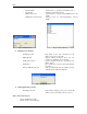
NVR 1. NVR General Settings If checked, will connect camera immediately (Used in Recording) Database Path has to be defined first. Exit the program after changing the Database Path. Synchronize if any changes have been made. Fig. 2. NVR Setup →General→Global Settings Press “General” on NVR setup window to start the General setup process (Fig. 2.): As it has been mentioned before, each of the components has its sub-components. 1.a. Global Settings 1.b. NVR Locations (only for “NVR Domain controller”) 1.
NVR 1.a. Global Settings Archive Storage – controls the video data retention time, the minimum space allowed for storage on the drive(s) and whether or not to overwrite the oldest information when the drive has reached its minimum available space. Detailed overview of the archive storage is provided in Fig. 3. Data retention time Archive Storage Minimum free drive space Fig. 3.
NVR o Port to Listen Port number used by all clients to connect to the Server. o Connect camera immediately - If checked, selected camera’s view will be shown immediately (The camera view on the recording page) - If unchecked, it gives the opportunity to the user, to connect/stop the selected camera’s view (cameras “recording page” Fig. 14.). o Resolve IP addresses Attempts to resolve the client IP address for statistical information.
NVR 1.b. NVR Locations (only for “NVR Domain controller”) When a request to connect to Domain controller is sent, this request can be: • • Either from a computer that is sending a connection request from within the same LAN (local IP address is used) Or from a computer that is sending a connection request from another LAN (external IP address is used). For more information please refer to How to set up NVR Domain Controller section provided later in this document. Fig. 4.
NVR 1.c. Camera Locations Setup “Location Name” and reference to “Location Map” if one exists. Map button on “Camera Locations” window Fig. 6. NVR Setup→General→Camera Locations Reference to this location can be made later in the NVR Cameras Setup (Description: Section 2.d.). Note: If user has assigned cameras to a map (done in section 2. d.), - Click on Map button on the camera locations window to view the list of assigned cameras Drag and drop them on their respective place on the map.
NVR 1.d. Voice Setup Voice Setup button (Fig. 7.) – These settings are not only for voice, but also for phone and e-mail on alarm. Voice Setup button brings up Alarm Server voice configuration dialog box (Fig. 7.1.) Voice test MUST be clicked if any changes were made to voice setup (Save) Fig. 7. NVR Setup→General→Voice Setup Fig. 7.1. Alarm Server Voice Configuration dialogue box 10 Click on this button brings up Alarm Server Voice Configuration window (Fig. 7.1.
NVR 1.e. FTP Server FTP Server receives ftp-sequences from the cameras (AXIS, JVC and SONY cameras only). For JVC and SONY cameras, ftp-sequence is treated as an alarm sequence. FTP-client settings must be setup inside the cameras in conjunction with FTP Server settings. In order for the FTP Server to work properly one needs to setup the path in the “Images path for FTP Server” field for each camera (see cameras, Fig. 11.).
NVR Fig. 9. NVR FTP Server dialogue box To setup FTP-clients inside the cameras, see the camera manual. NVR software has special needs for the “image file name” format settings. Some of which are as follows: - SONY cameras: “image file name” must have name “asony” with the suffix “Date/Time”. - JVC cameras: “image file name” must have name “alarm_jvc”.
NVR 1.f. Advanced By clicking on the “Advanced” tab in the GENERAL window, you will be able to set up some templates for the Recorder. Those setting and templates will be used tohelp you to create the “Recorder schedule”. Proxy Settings panel If a company uses web-proxy server that requires authentication to get to the Internet, proxy setting must be done in this panel.
NVR 2. NVR Cameras Setup To setup cameras, the “Cameras” tab on the NVR Setup Window must be selected (Fig. 11.). As it has been mentioned before, each of the components has its sub-components. Sub-components of the Cameras are as follows: 2.a. Cameras list 2.b. Cameras settings 2.c. Security and Alarm 2.d. Description 2.e. Recording 2.f. Tour (for PTZ cameras only) 2.h. Camera Tasks Fig. 11. NVR Setup→Cameras→Cameras Settings And “Sub-cameras” button 2.a.
NVR • In order to delete a camera, select a camera from the list of existing cameras, and click on the Delete button. Cameras can be sorted in a camera list. To start the sorting process, double-click on the camera list header (Fig. 11d) After double-clicking on the camera list, select any camera and move it up/down (Fig. 11.e.). To save the sorted list, click on “Save cameras order” button (Fig. 11.e.) To cancel the changes click “Cancel” (Fig. 11.e.). 2.b.
NVR • • • • Number of sub-cameras Defines the number of video-inputs this device has. Alarm inputs Defines the number of device Input ports. Alarm outputs Defines the number of device Outputs ports. Alarm ComPorts Defines the number of device COM-ports ports. • Sub-cameras Tab It is used to set sub-cameras parameters for video servers. (Fig. 11.) 9 Number Number of sub-cameras 9 Active Reflects if sub-camera is connected to the video input 9 PTZ Defines which sub-camera has Pan/Tilt/Zoom capability.
NVR Fig. 11.a. “Alarm Inputs” button Fig. 11.b. “Outputs” button Fig. 11.c. “ComPorts/MUX” button Note: Also, setup User name(s) and password(s) in the “Security” table (This depends on the individual camera settings. Usually Axis cameras require this setting.) Double click here to start sorting the cameras (Fig. 11.e.). Get appropriate driver to deal with this device Fig. 11.d.
NVR Move Up Move Down “Cancel” to go back to Fig. 9d. Save Select a camera to move. Fig. 11.e. Sorting cameras For SONY and AXIS cameras it is recommended to use “Determine camera driver” button. You need to setup only name, type, address and port and proxy type for the device and press “Determine camera driver” button. If device has a password and you have not set it jet you will be asked about it and the password will be saved in “names and password: fields (see Fig.12).
NVR 2.c. Security and Alarm Fig. 12.NVR Setup→Cameras→Security and Alarm • Names and Passwords, for access to each camera. • Actions on Alarm: - Check status task, user can select a task from the pull down menu to be executed when camera status changes (checks the physical status of the camera, if any problem is detected, executes the selected task). - FTP alarm task, user can select a task from the pull down menu (This is used when Images path for FTP server is set for a camera.
NVR 2.d. Description Fig. 13. NVR Setup→Cameras→Description When a specific alarm event occurs, information provided in Description window will be used to inform the user of the alarm event (Fig. 13.). Description window contains the following information: • • • • • • Camera location: The location in which camera resides.
NVR 2.e. Recording Recorder is part of the NVR software. It is responsible for getting the video streams from the cameras according to the schedule (refer to schedule box in recording). Also, it writes the information into the archive. Recorder can supervise AXIS, JVC, SONY, Panasonic, Pixord, IDVIEW, EverFocus (EDR400), ENRITEC (DigiOp), Convision and some other Internet-cameras.
NVR Many lines can be added to the schedule for each sub-camera. It is worth mentioning that, lines are the scheduled recordings, located at the schedule box (Fig. 14.). Different sections are to be set for each line of the schedule (Fig. 14): 1. 2. 3. 4. 5. 6. 7. 8. Schedule section - Click on “Add”, “Save”, or “Delete” buttons to add, save, or delete schedules respectively.
NVR Motion Settings Disabled sub-region To move, click inside the ROI and drag Active subregion To resize, click on the corner and drag Fig. 15. Motion Settings This screen enables the user to setup motion detection parameters for each line of the schedule (Fig. 15.). o Draw ROI In order to draw ROI (Region-of-Interest), start with left-top corner, press left-mouse-button and drag mouse down to the right. A red box will appear on the picture that is referred to as ROI.
NVR 2.f. Tour (for PTZ cameras only) Touring can be setup and started for any PTZ-capable AXIS, JVC, or SONY cameras. This must be done according to specific schedules. In order to enable the “Tour” option, check the “With PTZ” box on the Cameras settings page (Fig. 11.). Cam Tour application is a part of NVR software that provides all the necessary settings for touring. In order to setup a tour, user must: a. b. Setup tour Setup schedule Fig. 16. NVR Setup→Cameras→Tour→Setup Tour a.
NVR 2.h. Camera Tasks This allows user to setup tasks which can be remotely executed by the Remote Client when the appropriate camera (or video input) becomes active on the single-screen of the Client . You just need to move (see Fig.16a) all the necessary tasks from “Available Tasks” list to “Linked tasks” list. Fig. 16a.
NVR b. Setup Schedule Any of the previously setup tours, can be used in the tours schedule. Sub-cameras can be added to the tour schedule by selecting add button. The setup schedule setting also provides delete and save option (Fig 17.b. & 17.d.) To Setup a schedule: • Click on “ADD” button. • Select “No time restrictions” or “Restricted Between”. • Select a previously setup tour from the “Tour” pull down menu.
NVR 3. NVR Users Setup To setup users, click on “Users” option provided on the NVR Setup Window. As it has been mentioned before, each of the components has its sub-components. The sub-components of the Users are as follows: 3.a. User information 3.b. Groups of cameras 3.c. Tasks 3.d. Billing information and restrictions 3.a. User Information Fig. 18. NVR Setup→Users→User Information Add, Dup, Save, and Delete buttons are used to add, duplicate, save, or delete users respectively.
NVR There are two kinds of users available: Master User and Exclusive Master User. While an exclusive master user selects a camera, that camera will not be available to other users. It is worth mentioning that “Exclusive Master User” has the ability to halt any active user. To assign a camera to the user, camera has to be moved from the available cameras list to the assigned camera list by clicking on “>” button.
NVR 3.c. Tasks Fig. 19a. NVR Setup→Users→Tasks It is possible to assign tasks to the user.
NVR 3.d. Billing Information and restrictions To setup restrictions for the user “Billing Information and Restrictions” option is provided (Fig. 20.). Fig. 20. NVR Setup→Users→Billing Information and Restrictions The information in “Full Name”, “Time block” and “Fee” fields are selected from the settings in the “Billing module”. Up to three restricted intervals are available when the user is banned to reach the Server.
NVR 4. NVR Tasks Tasks are used in: • Monitoring section of the “NVR Locations”, when an NVR does not respond to Domain controller (Section 1.b. Fig. 5. and How to set up NVR Domain Controller). • Alarm section of the cameras “Recording” (Section 2.e. Fig. 14.).
NVR New → “Action” 4.a. Record Camera Click here to bring up PTZ control dialogue box Fig. 22. New → Action →Record Camera Action (Record Camera) Setup: • • • • • • • • • • Camera: Select a camera for this action. Set camera in position - Pan/ Tilt/ Zoom - Or Preset Record - Image size - Compression - FPS - Frames - Sec. Take Alarm shot: For PTZ cameras; if checked, takes alarm shots.
NVR 4.b. Move Camera Click here to bring up PTZ control dialogue box Fig. 23. New → Action →Move Camera Action (Move Camera) Setup: • • • • • • Camera Set camera in position - Pan/ Tilt/ Zoom - Or Preset Dwell time(s): The time in which camera stays in a selected position. Reset camera in position - Pan/ Tilt/ Zoom - Or Preset Connect/Stop: When camera is selected, press connect button in order to connect to that camera (press stop to disconnect from the selected camera).
NVR • • • • • Pan/ Tilt/ Zoom Get PTZ: When clicked, provides the PTZ value of the position that camera is pointing to. Set PTZ: Can be used in order to change PTZ values. Zoom IN/OUT Go to Preset: Choose a preset position from the pull down menu and click on “Go to Preset”; as a result camera will point to the selected preset position. Home position Direction control tool: Can be used to control the direction of the camera towards Right, Left, Up, and Down. • • 4.c. Control Relay e.g. 5 sec. Fig. 25.
NVR 4.d. Control Tour Start tour Stop tour Fig. 26. New → Action →Control Tour When “Start tour” is selected, a pre-selected tour will start. When “Stop tour on camera” is selected, the tour that is running will be stopped. Action (Control Tour) Setup: • • • • Start Tour: when selected, a camera and a tour must also be selected from the pull down menu Stop Tour on camera: when selected, a camera must be selected from the pull down menu Reset touring after (e.g.
NVR New →“Notification” 4.e. Network Client Message box Fig. 27. New → Notification →Network Client A sample text message that is sent to a client is depicted in Fig. 27.1. Notification Via Message Setup: • • • • • • • Address: address of the client that Domain controller wants to send the message to. Port: Client port number. Proxy address Proxy port Send always: If checked, sends the message to the client. Note: User can create multiple client notifications (network client) under one Task.
NVR 4.f. Phone Fig. 28. New → Notification →Phone Notification via Phone Setup: • Location to phone message from • Phone/Pager to call • Number of attempts • Always call 4.g. Email Fig. 29. New → Notification →Email Notification via Email Setup: • Location to mail message from • Email address (es): Email address of the party, which the notification will be send to • Subject: Email subject. • Message: Email message that will be send to client.
NVR 4.h. Speak Message box containing Sample message. Fig. 30. New → Notification →Speak Sound Notification setup: • Location to play message from: Address of the location in which message will be played from. • Message can be changed automatically: - If checked, an automatic default message will be played. Thus, the message written in message box to be played as sound notification will be ignored.
NVR 5. NVR IO Devices If you have appropriate license you will see “IO Device” tab and will be able to work with: - Gameport - IOBoard ET-PCI16IO - Paradox Spectra device You have to create right descriprion of the device you are going to use (see Fig. 30.a) Fig. 30.a. IO Device Setup. You can assign task to any event device could create. On receiving signal from the device appropriate task will be executed.
NVR 6. NVR Monitor Monitor allows the user to observe NVR components (Fig. 31.). Recorder is running (blue). It will be restarted if Check Alarm is stopped (red). Health Monitor button allows you to assign tasks to monitor NVR components Log Viewer button allows you to see log information about tasks Fig. 31. NVR Setup→Monitor During normal operation this window could be left open and available. The status of all the cameras that have been installed on the NVR can be seen on NVR monitoring window.
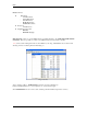
NVR 7. NVR Reports This advanced feature allows the user to run reports that show when various users have been authenticated and logged on to the NVR. It displays date, time, and the host address. Searches can be made using the following criteria: - USER NAME HOST ADDRESS Date range Click Run to view the report. Fig. 32.
NVR Supplementary Software Port Mapper Setup Fig. 40. Port mapper To map a port use the Add/Delete/Edit buttons (Fig. 40.) After pressing one of those buttons, port mapping dialog box will appear (Fig. 41.). Fig. 41. Port mapping dialogue box Fill in the required information in the Port Mapping dialog box (Fig. 41.). To activate mapping CHECK the required port (Fig. 41.) and press the start button (Fig. 40.). To stop the program, use the “Exit” button only.
NVR Note: In order to edit the line, stop (inactivate) listening to the port you want to edit.
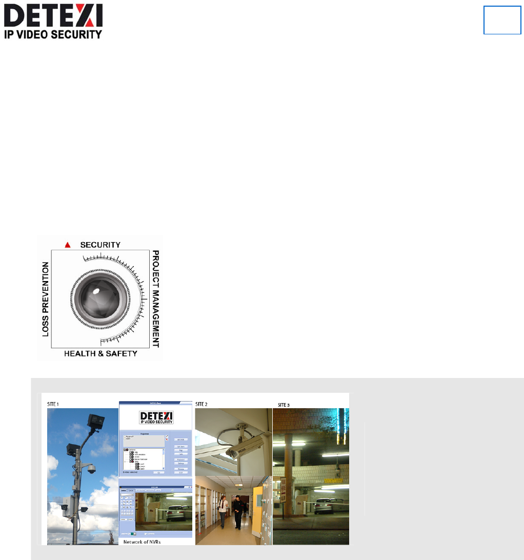
NVR Network of NVRs There are two challenges that video surveillance systems are facing today, namely scalability and reliability. Large organizations that have multiple sites in local or remote locations could have from ten to over a thousand cameras to manage. The approach in the past was to have islands of standalone systems that required time consuming and inconvenient maintenance and management.
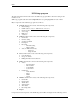
NVR Building NVR Domain Whether you have several sites or a single site with hundreds of cameras, you can now plan a security management strategy. You can create a set of NVRs by dividing cameras by groups, and assigning each group to a corresponding NVR. Each particular NVR is responsible for its group of cameras and carries the duty of recording, touring, and alarming functions. We use an NVR Domain Controller to manage the set of NVRs (Fig. 42.) Fig. 42.
NVR NVR Domain Controller gains knowledge of all NVRs in its domain, which in turn leads to the realization of the existing cameras in the corporate network. NVR Domain Controller can: Remotely Create and Update cameras list on any NVR in Domain Remotely Create and Update recording schedule for each camera Remotely Create and Update touring schedule for each camera Obtain and update remote User List from any NVR in Domain as well as support its own local user list.
NVR If the site is accepted, it becomes part of the NVR’s Domain Network. Once became a part of NVR’s domain Network, any changes on NVR in cameras table (edit/add /delete) will be mirrored on Domain Controller. Domain model depends on the connection (locally or through the Internet) between NVR and Domain Controller. This is important specifically while making changes to camera setting.
NVR Disable remote site. It is useful if there are technical problems connecting to this site. Changes to settings can be saved. Fig. 44. NEW connection request Information about the cameras from remote site is copied using this option. There are no restrictions about using this option.
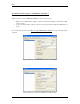
NVR Updating Camera lists across Domain If Remote NVR is in “Normal” mode, you can remotely update Cameras list. To do this, find remote location (e.g. Graphics), and change camera setting locally. (Fig. 45.) Remote Location Fig. 45.
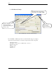
NVR Updating User lists across Domain Fig. 46. NVR Setup → Users → User Information If Remote NVR is in “Normal” mode, you can remotely update Users list. To update the USER, select the location that needs to be updated from the “User” table (Fig. 46.) First time users will be asked for the authentication information by the system (Fig. 47.) Fig. 47. Authentication window for Remote User (Always contains the name of the remote user, e.g. Graphics.
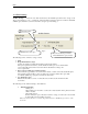
NVR Troubleshooting across Domain When connection between ” NVR domain controller” and another NVR (child) in its domain is broken, the system has to have the ability to continue its work and do the synchronization later. In case of a “broken connection” between Domain controller and a remote site such as site “A”: 1. If o The whole situation is looked at from remote site “A” standpoint, o User (e.g.