
User guide


NVR
16
• Number of sub-cameras
Defines the number of video-inputs this device has.
• Alarm inputs
Defines the number of device Input ports.
• Alarm outputs
Defines the number of device Outputs ports.
• Alarm ComPorts
Defines the number of device COM-ports ports.
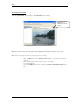
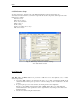
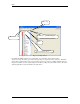
• Sub-cameras Tab
It is used to set sub-cameras parameters for video servers. (Fig. 11.)
9 Number
Number of sub-cameras
9 Active
Reflects if sub-camera is connected to the video input
9 PTZ
Defines which sub-camera has Pan/Tilt/Zoom capability.
9 Alive
Defines if it is necessary to check “video-signal-lost” for sub-camera
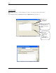
• Alarm Inputs Tab
It is used to set device Inputs’ properties (Fig. 11.a.).
9 Input number
9 Name
Any unique name, (If the standard names are not preferred)
9 Normal Status
Open/Closed.
• Outputs Tab
It is used to set Outputs’ properties (Fig. 11.b.).
9 Name
Any unique name, (If the standard names are not preferred)
9 Output number
9 Normal status
ON/OFF
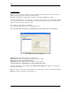
9 Behavior
If “Toggle”, it will work similar to a light contact.
If “Momentary”, it will work similar to a door contact.
9 State on close
Unchanged, light must be turned on/off manually.
ON,
light will turn on automatically upon leaving the camera.
OFF, light will turn off automatically upon leaving the camera.
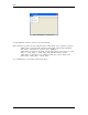
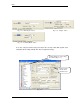
• ComPorts/MUX Tab
Sets up the type of multiplexer attached to one of the video COM ports. (Fig. 11.c.)
9 ComPort number
9 Multiplexer
Defines device type that is connected to the selected Com-Port
9 Sub-camera
Defines video input associated with the selected Com-Port.
Note: A special setup must be done inside the Axis server to make the multiplexer work
properly.