
User guide


DETEXI NVR 85 - 169
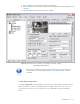
9 Images must be either 24 x 24 px BITMAP files (24-bit) or 16 x 16 px ICO files.
9 A few icons of this type are available on the installation CD in the Utilities/NVR Output Icons
directory.
4. Check the Transparent checkbox to convert BITMAP image to have a transparent background.
9 Top-left pixel color is considered as a background.
5. For momentary relay types, define a custom momentary delay before the output is turned back off.
6. Click Save button to save a new relay action button.
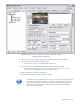
7. Select a relay action button for use from the list and click Select button.
9 Click Cancel button to return without changes.
9 Click Default button to return to default settings.
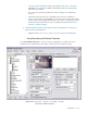
Fig 55. NVR Control Center — Cameras Settings — Outputs
(To customize a relay Action button click on it to launch Relay Types dialog.)
4. Control Relay
After an IP device outputs were defined in the NVR Control Center — Cameras — Cameras
Settings they are ready for use in tasks triggered by alarms/events, or manually by operators in the
DETEXI Client.
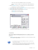
9 Relay Action buttons will be available on the DETEXI Client’s camera live view allowing for external
devices (relays) to be triggered (Fig 56).
9 The momentary relay only has been enabled for the output — only one relay
action button is visible.
9 If multiple outputs are connected to and configured on the camera, a drop-down
list to choose the output number from will be available. When an output number is
chosen, the configured control buttons will be displayed for use.