
Specifications

MAINTENANCE
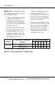
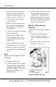
Method Two — Method two allows
you to adjust all the valves using just
two crank sh aft positions.
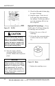
1. Using the cranking tool, turn the
crankshaft until cylinder #1 is
at the ignition TDC position (all
valves are closed) and cylinder
#6 is at the val ve overlap position
(all valv es are o pen).
2. Check the valves listed in Table
20 in the "Ignition TDC" row of
and adjust them (if necessary),
using the procedures under the
headings "Checking Valve Lash"
and "A d justing Valve Lash."
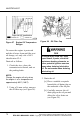
3. Using the cranking tool, turn the
crankshaft until cylinder #6 is
at the ignition TDC position (all
valves are closed) and cylinder
#1 is at the valve overlap position
(all valves ar e open).
4. Using the same procedure, check
the valves listed in Table 20 in the
"Valve Overlap" row and adjust
them (if necessary), using the
procedures under the headings
"Checking Valve Lash" and
"Adjusting Valve Lash."
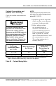
Cylinder Valve Types*
Engine
Cylinder #1 Crankshaft
Position
1234
5
6
Ignition TDC I/E
IEIE
—
MBE 4000
Valve Overlap
—
EIEI
I/E
*I = Intake Valve, E = Exhaust Valve
Table 20 Valve Adjustment — Method Two
72 All information subject to change without notice. (Rev. 04/08)
DDC-SVC-MAN-0056 04/08 Copyright © 2008 DETROIT DIESEL CORPORATION