
Manual

QTS Series
40
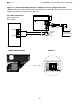
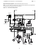
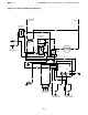
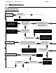
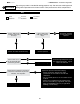
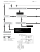
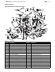
Figure 5.1 • Burner Assembly Components
Replacement Parts
5.0 Maintenance • Heater Components and Parts List
Part No. Description Part No. Description
TP-13 #8 x 1/2” Self-Drilling Screw TP-3022 #8 x 1/2” Black Sheet Metal Screw
TP-33B 1/2” Shut-Off Valve TP-3055 2 Prong Ignition Electrode (2)
TP-62 #8 x 1/2” Aluminized Sheet Metal Screw TP-6001 Control Mounting Panel
TP-68B Large Strain Relief Bushing (2) TP-6002A Burner Box Left Side Panel
TP-83 Stainless Steel Flexible Gas Connector TP-6003 Burner Box Right Side Panel
TP-84 1/2” Female to Male FC-12 Flare Fitting TP-6004 Burner Box Front Panel w/9 Weld Studs
TP-204 Gas Orifice (2) - Specify Size TP-6005 Burner Box Top Cover
TP-222 Flame Sensing Rod (2) TP-6006 Burner Box Bottom Panel
TP-337 Electrical Plastic Bushing (3) TP-6007 Burner Box Rear Panel, Upper
TP-826 40VA Transformer-120V Pri./24V Sec. TP-6008A Burner Box Rear Panel, Lower
TP-828 24VAC Indicator Light TP-6009 Burner Center Panel
TP-933 6-ft Black 120VAC Power Cord TP- 6 011 Burner Mounting Holster (2)
TP-934 6-ft Yellow 24VAC Control Cord TP-6012 Burner and Ignition Supporting Frame (2)
TP-1264A Air Proving Switch TP-6013 Service Access Handle
TP-1325 24VAC Switching Relay TP-6015A Fan Motor Assembly
TP-1528 Post Purge Timer TP-6019 Exhauster Collector Box
TP-3014 Combustion Air Inlet Collar w/ Screen TP-6020A Fan Restrictor Plate - 40
Chart 5.1 • Parts List
3014
6007
6013
6008A
6025
6005
6070
6011
6015A
6069
6065
6070
6011
222
3055
3055
6053
6053
222
6003
6012
6012
6056
6055
83
1264A
1325
1528
6225
826
6201
6001
33B
6048
84
933
934
6055
6056
828
6042
68B
6074
6006
6002A
6047
6040,6041
6023
6044
204
6009
6020A,B,C
6076
6004
13,62
6022
337
6024
3022
6051
6019,
6021C