
Owner's manual


WARNING
!
Tube Heater General Manual
12
Suspension of the heater must conform to applicable codes referenced in the Safety section and
these instructions.
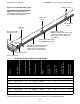
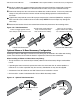
Lay all radiant tubing out in the following order. Position tubes in approximate location (see figure 3.4).
• 10 ft. primary combustion chamber.
• If applicable, the secondary 10 ft. aluminized treated steel combustion chamber (150-200 MBH
models only). Refer to the Specifications Chart in the Series Insert Manual to determine if a second
combustion chamber is required for your model heater.
• Radiant emitter tubes.
Important! 150,000-200,000 BTU/h models must use the 10 ft. titanium alloy treated combustion
chamber as the first tube downstream of the burner control box. The combustion chamber has
an orange identification sticker located on the swaged end of the tube.
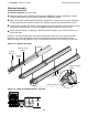
Stainless Steel Heaters must use the 409 Series stainless steel combustion chamber as the
first tube downstream of the burner control box.
2
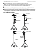
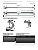
Mark locations for hanging points.
NOTE: If the available hanging points do not allow for the recommended spacing then additional
hangers (P/N: TP-19B) may be necessary.
• The spacing between the burner control box mounting brackets and the first hanger should be
approximately 2’-4”.
• The space between the first two hangers placed on the first tube, should be approximately 8’-10”.
• The space between hangers thereafter, one per tube, should be approximately 9’-8”.
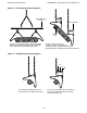
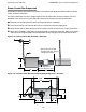
Hanger Placement and Suspension
3.0 Installation • Hanger Placement and Suspension
Improper suspension of the tube heater may result in collapse and being crushed. Always
suspend from a permanent part of the building structure that can evenly support the total
force and weight of the heater.
Failure to maintain minimum clearance to combustibles may result in fire and/or explosion,
property damage, serious injury or death. Always maintain minimum clearances and post
clearance safety limit signs or the clearance safety tag where needed.
1