
Owner's manual


Tube Heater General Manual
20
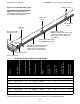
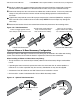
Figure 3.16 • Reflector Assembly
Reflector Assembly
3.0 Installation • Reflector Assembly
Reflector
4” Overlap
Reflector Center
Support
Radiant
Tube
Hanger
and Chain
Reflector End Cap
Reflector Tension
Spring
Clips
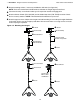
To install the reflectors (see figure 3.16):
Attach the reflector center supports onto radiant tubes. NOTE: On models equipped with a single
reflector center support, place at mid-point of primary combustion chamber.
2
Slide each reflector section through the hangers and adjust the reflector tension spring (if applicable)
into the V-groove on the top of the reflector. The reflectors should overlap approximately 4 inches.
3
To prevent the reflectors from shifting, secure the reflector sections together using sheet metal screws,
except at the expansion joint (see chart 3.6). NOTE: Installer to supply sheet metal screws.
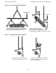
4
Attach reflector end caps (if applicable), with polished finish inward, to each end of the reflector run.
Secure with clips.
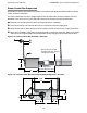
Reflectors, and reflector accessories, direct infrared energy to the floor level. The reflector assembly
depends on the heater configuration, proximity to combustibles and space surrounding the heater.
Before you begin assembly, determine if the use of reflector accessories are necessary (see chart 3.5).
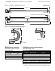
13.75”
Figure 3.17 • Width of Installed Reflector - Top View
1