
Technical data


2
TABLE DES MATIÈRES
SECTION 1 INSTALLATION .................................... 3
1.1 DANGER, WARNING AND CAUTION .................. 3
1.2 HEATING WITH HOT WATER .............................. 3
1.3 DELIVERY ............................................................. 3
1.4 INSTALLATION.....................................................3
1.4.1 Positioning.............................................................. 3
1.5 CLEARANCES ...................................................... 4
1.6 DISTRIBUTION SYSTEM ...................................... 4
1.7 INSTALLATION OF THE BOILER ........................ 6
1.8 ELECTRIC POWER SUPPLY................................ 6
1.8.1 Connecting the Circulating Pump ........................... 6
1.8.2 Connecting the Thermostat .................................... 6
1.8.3 Connecting the Outdoor Sensor ............................. 6
SECTION 2 OPERATION......................................... 7
2 ADJUSTMENTS AND START-UP......................... 7
2.1 MECHANICAL HIGH LIMIT................................... 7
2.2 ELECTRONIC CONTROL ..................................... 7
3 SECTION - MAINTENANCE................................ 11
4 SECTION - INFORMATION................................. 11
5 SECTION - TECHNICAL DATA........................... 12
6 SECTION - REMPLACEMENT PARTS............... 17
INDEX DES TABLEAUX
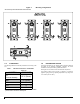
Table 1. Minimum clearances to combustible materials..4
Table 2. Hydra Revolution – Technical specifications...12
Table 3. Parts list ..........................................................18
Table 4. Parts list ..........................................................20
INDEX DES FIGURES
Figure 1: Mounting configurations ....................................4
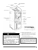
Figure 2: Boiler components ............................................5
Figure 3: Power Stealing Thermostat Resistance ............6
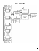
Figure 4: Navigation in Menus .........................................9
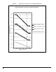
Figure 5: Modulation in function of the exterior
temperature.....................................................10
Figure 6: Boiler Dimensions ...........................................13
Figure 7: Typical Diagram of a Single Zone Installation .14
Figure 8: Multi-zone Diagram with more than one
Circulator.........................................................14
Figure 9: Multi-zone diagram with Motorized Valves......15
Figure 10: Dual-energy installation...................................15
Figure 11: Electrical Diagram...........................................16
Figure 12: Exploded Vue (3-4 elements)..........................17
Figure 13: Exploded Vue (5-6 elements)..........................19