
Technical data

6
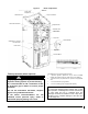
1.7 INSTALLATION OF THE BOILER
At the time of installation, the following steps should be followed.
Refer to Figure 5,6,7,8 and 9.
1. Choose an appropriate location. Mount the boiler securely on
the wall, with the help of the mounting plate. Ensure that it is
level and that the minimum clearances are observed;
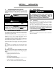
2. Install the drain valve and the safety valve according to the
mounting configuration as shown in Figure 1;
3. An air vent should be installed on the unit if installed upside
position; in horizontal mounting position, cork the hole with the
¼’’ cap provided.
4. Install the water supply and return piping with the 1” NPT fitting;
5. The heating supply line must include:
a. 1 circulator along with 2 maintenance valves;
b. 1 automatic pressure reducing valve adjusted to 12 psi,
with a shut-off valve on the return water line;
c. 1 expansion tank;
d. 1 automatic vent.
6. In order to ensure satisfactory water flow, the friction in the
piping system must not exceed the capacity of the circulator;
7. After having completed all piping connections, run water
through the system and purge the air. The automatic vent
should be in operation.
Note: Remove the plastic cover and check to see if the elements
are watertight.
1.8 ELECTRIC POWER SUPPLY
All electrical wiring must conform to the standards and regulations in
force and the Canadian Electrical Code CSA C22.1.
Electrical power to the boiler must come from a 120/240V 60 Hz or
208V 60 Hz, single phase, 3-wire, grounded circuit, protected by an
appropriately sized breaker, based on the total rating of the boiler.
When using 208V, change the connector’s position at the primary of
the transformer. Refer to the boiler nameplate and the technical
specifications in this manual to select the proper breaker and wire
size. Use cable rated at 60°C or higher.
For models with a power of 24KW and above, two separate
conductors are required. Make sure to turn off both circuits when
working in the appliance.
WARNING
Fire Hazard.
The conductor sizing must conform to the last
edition of the local or national codes.
Failure to follow this rule can result in death, bodily
injury and/or property damage.
Power supply to the unit can be made using copper or aluminum
wires. The wire size must be decided in accordance to unit power
consumption, the over current protection type and capacity, the wire
type and length, and the environment where the unit is installed. If
an aluminum wire is used, other precautions (such as the use of a
DE-OX inhibitor) must be taken to insure the conformity of the
installation. In all cases, all the factors affecting the wire gauge must
be considered and the installation codes followed.
The exterior of the unit must have an uninterrupted ground to
minimize the risk of bodily harm. A ground terminal is supplied with
the control box for that purpose.
In the event that wires inside the unit require replacement, these
must be as same type as originals. (Copper wiring only)
1.8.1 Connecting the Circulating Pump
Connect the circulating pump on 120V connections points identified
N for neutral and P for controlled 120V output in the control panel as
shown in Figure 2. The electronic control is designed to operate the
circulator on thermostat demand, with a heat purge delay at the end
of heating cycle or continuous flow. Refer to the electronic control
section to learn how to configure this function.
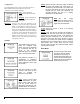
1.8.2 Connecting the Thermostat
A 150 OHMS – 10W must be installed if a power stealing thermostat
is used. This resistance must be connected to C-W as shown in
Figure 3:
Figure 3: Power Stealing Thermostat
Resistance
Single heating zone
Connect the low voltage thermostat to C(T)-W(T) terminals located
inside the control panel. See Figure 4.
Multiple heating zones
Connect the contacts of the motorized valves or pump controls to
C(T)-W(T) terminals inside the control panel. See Figure 5 and 6.
1.8.3 Connecting the Outdoor Sensor
Mount the sensor on an outside wall, protected from direct sunlight,
so that it will accurately measure the outside temperature. Install 2
#20 wires between the outdoor sensor and the terminals identified
as EXT1 and EXT2 inside the control panel of the boiler.