MICROWAVE OVEN BASIC : SMH7178STD MODEL : SMH7178STE SERVICE MICROWAVE OVEN Manual CONTENTS 1. Precaution 2. Specifications 3. Operating Instructions 4. Disassembly and Reassembly 5. Alignment and Adjustments 6. Troubleshooting 7. Exploded Views and Parts List 8. PCB Diagrams 9. Schematic Diagrams SEA 10.
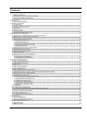
Contents 1. Precaution 1-1 Safety precautions 1-2 Special Servicing Precautions (Continued) 1-3 Special High Voltage Precautions 2. Specifications 2-1 Table of Specifications 3. Operating Instructions 3-1 Control Panel 3-2 Features & External Views 3-3 Accessary 3-4 INSTALLATION 3-4 REUSABLE GREASE FILTERS 4.
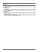
Contents 7-3 Control & Door Parts List 7-4 Standard Parts List 8. P.C.B Diagrams 8-1 P.C.B Diagrams 8-2 P.C.B Parts List 8-2 P.C.B Parts List(continued) 9. Schematic Diagrams 9-1 Schematic Diagrams 10.
PRECAUTIONS TO BE OBSERVED BEFORE AND DURING SERVICING TO AVOID POSSIBLE EXPOSURE TO EXCESSIVE MICROWAVE ENERGY (a) Do not operate or allow the oven to be operated with the door open.
1. Precaution Follow these special safety precautions. Although the microwave oven is completely safe during ordinary use, repair work can be extremely hazardous due to possible exposure to microwave radiation, as well as potentially lethal high voltages and currents. 1-1 Safety precautions ( ) 1. All repairs should be done in accordance with the procedures described in this manual. This product complies with Federal Performance Standard 21 CFR Subchapter J(DHHS). 11.
1-2 Special Servicing Precautions (Continued) 17. When checking the continuity of the witches or transformer, always make sure that the power is OFF, and one of the lead wires is disconnected. 18. Components that are critical for safety are indicated in the circuit diagram by shading, or . 19. Use replacement components that have the same ratings, especially for flame resistance and dielectric strength specifications.
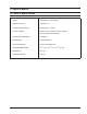
2. Specifications 2-1 Table of Specifications TIMER 99 MINUTES 99 SECONDS POWER SOURCE 120V 60Hz, AC POWER CONSUMPTION MICROWAVE : 1,650W OUTPUT POWER FROM 100 TO 1100W(10 LEVEL POWER) (IEC-705 TEST PROCEDURE) OPERATING FREQUENCY 2,450MHz MAGNETRON OM75P(10)ERHN COOLING METHOD COOLING FAN MOTOR OUTSIDE DIMENSIONS 2914/16”(W) x 1515/16”(H) x 1511/32”(D) mm NET WEIGHT 58.4 lbs SHIPPING WEIGHT 64.
3. Operating Instructions 3-1 Control Panel 1. Sensor Reheat 2. Power Defrost Sets weight of food to be defrosted. 3. Sensor Cook Buttons p.11 Sensor settings to cook popular foods. 1 13 4. Handy Helper, Kids Meals, Snack Bar 2 11 5. More/Less Selects type of dish to be reheated. Increase or decrease cooking time. 6. Number Buttons 3 Set cooking times or amounts and power levels other than high. 7. Power Level Press this pad to set a power level other than high. 4 8.
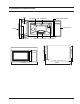
3-2 Features & External Views Door Ventilation Holes Oven Light Safety Interlock Holes Control Panel Handle 417.25mm Glass Tray Guide Roller Intake Holes 405mm Door Latches 758.
3-3 Accessary Glass tray Roller guide ring -6-
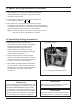
3-4 INSTALLATION The Microwave Oven is supported by a special bracket assembly (mounting system) supplied with the oven. The bracket assembly must be mounted to the wall with toggle bolts through the wall, and a lag screw into a wall stud. After the bracket assembly is installed, the unit can be slid over the two rails of the bracket assembly. Two bolts are run down through the cabinet bottom and into the oven case to pull the oven up against the cabinet bottom.
3-5 REUSABLE GREASE FILTERS The metal filter trap grease released by foods on the cooktop. They also prevent flames from foods on the cooktop from damaging the inside of the microwave. Charcoal Filter For this reason, the filters must ALWAYS be in place when the hood the vent fan is used. The grease filter should be cleaned once a month, or as needed. REMOVING CHARCOAL FILTER To remove the charcoal filter, disconnect power at the main fuse or circuit breaker panel or pull the plug.
4. Disassembly and Reassembly 4-1 Replacement of Magnetron, Motor Assembly and Lamp Remove the magnetron including the shield case, permanent magnet, choke coils and capacitors (all of which are contained in one assembly). 1. Disconnect all lead wires from the magnetron and lamp. 2. Remove a screw securing air cover. 3. Remove the air cover. 4. Remove screws securing the magnetron to the wave guide. 5. Take out the magnetron very carefully. 6. Remove tow from the back panel of fan motor assembly. 7.
4-3 Replacement of Door Assembly 4-3-1 Removal of Door “C” Insert flat screw driver into the gap between Door “A” and Door “C” to remove Door “C”. Be careful when handling Door “C” because it is fragile. Then remove the door assembly. Door "A" Door "C" 4-3-2 Removal of Door “E” DOOR "E" Following the procedure as shown in the figure, insert and bend a thin metal plate between Door “E” and Door “A” until you hear the ‘tick’ sound. - Insertion depth of the thin metal plate should be 0.5mm or less.
4-3-4 Reassembly Test After replacement of the defective component parts of the door, reassemble it and follow the instructions below for proper installation and adjustment so as to prevent an excessive microwave leakage. 1. When mounting the door to the oven, be sure to adjust the door parallel to the bottom line of the oven face plate by moving the upper hinge and lower hinge in the direction necessary for proper alignment. 2.
4-6 Replacement of stirrer motor 1. Disconnect power and remove grille screws(2). 2. Remove grille and the bracket duct upper screw(1). 3. Remove the bracket duct upper and disconnect the stirrer motor wire. 4. Remove stirrer motor screws(1) and lift up stirrer motor after turn left. STIRRER MOTOR 4-7 Removal of stirrer The stirrer is located on the upper side of the cavity. The oven uses a top feed wave guide. 1. Disconnect power and open the door. 2. Remove the clip and turn the stirrer cover left. 3.
4-8 Replacement of Control Circuit Board 4-8-1 Removal of Control Box 1. Disconnect power and remove grille. 2. Remove a screw securing the control box assembly. 3. Be sure to ground any static electric charge in your body and never touch the control circuit. 4. Disconnect the connectors from the control circuit board. 4-8-2 Removal of P.C.B Assembly 1. Pull the lever end of the plastic fastener and remove the Flexible Printed Circuit(FPC) of membrane panel. 2.
5. Alignment and Adjustments PRECAUTION 1. High voltage is present at the high voltage terminals during any cook cycle. 2. It is neither necessary nor advisable to attempt measurement of the high voltage. 3. Before touching any oven components or wiring, always unplug the oven from its power source and discharge the high voltage capacitor. 5-1 High Voltage Transformer 1. Remove connectors from the transformer terminals and check continuity. 2.
5-4 High Voltage Capacitor 1. Check continuity of the capacitor with the meter set at the highest resistance scale. 2. Once the capacitor is charged, a normal capacitor shows continuity for a short time, and then indicates 9MΩ. 3. A shorted capacitor will show continuous continuity. 4. An open capacitor will show constant 9MΩ. 5. Resistance between each terminal and chassis should read infinite. 5-5 High Voltage Diode 1. Isolate the diode from the circuit by disconnecting its leads. 2.
5-8 Vent Exhaust Blower Motor THIS COMPONENT REQUIRE REMOVAL OF MICROWAVE OVEN FROM INSTALLATION FOR SERVICING. The blower is a two speed (HI-LO) capacitor run blower assembly located on top of the microwave oven. The blower is operated by low voltage relays located on the smart board. The blower motor has 3 winding which can be tested for continuity from the front by removing the top grille and opening the control panel.
5-9 Thermal Cutout (TCO’S) There are 4 different thermal cutouts in this unit with 4 different purposes. They are : 1. Oven thermal cutout (flame sensor), on cavity top. 2. Hood thermal cutout, inside control area on duct. 3. Bottom thermal cutout, on floor of control area. 4. Magnetron thermal cutout, on magnetron.
5-9-3 Bottom Thermal Cutout This cutout will protect the touch control from excessive heat by turning the vent fan on at low speed. If the surface units of the range are used for long periods of time heat will build up and could damage the microwave control. In order to prevent this a thermal cutout is installed on the duct behind the control. This cutout will close (158°F/70°C - vent fan energized)and open (104°F/40°C - vent fan de-energized) depending on temperatures it sense.
5-9-5 Magnetron Thermal Cutout The magnetron thermal cutout is located above the leads to the magnetrons. It is designed to prevent damage to the magnetron if an overheated condition develops in the tube to cooling fan failure, obstructed air ducts, dirty or blocked air intake. Under normal operation, the magnetron thermal cutout remains closed. However, when abnormally high temperatures are reached within the magnetron, the magnetron thermal cutout will open at 320°F(160OC) causing the oven to shut down.
5-11 Output Power of Magnetron CAUTION MICROWAVE RADIATION PERSONNEL SHOULD NOT ALLOW EXPOSURE TO MICROWAVE RADIATION FROM MICROWAVE GENERATOR OR OTHER PARTS CONDUCTING MICROWAVE ENERGY. The output power of the magnetron can be measured by performing a water temperature rise test. Equipment needed : * Two 1-liter cylindrical borosilicate glass vessel (Outside diameter 190 mm) * One glass thermometer with mercury column NOTE: Check line voltage under load. Low voltage will lower the magnetron output.
5-12 Procedure for Measurement of Microwave Energy Leakage 1) Pour 275±15cc of 20±5°C(68±9°F) water in a beaker which is graduated to 600cc, and place the beaker in the center of the oven. 2) Start to operate the oven and measure the leakage by using a microwave energy survey meter. 3) Set survey meter with dual ranges to 2,450MHz. 4) When measuring the leakage, always use the 2 inch spacer cone with the probe. Hold the probe perpendicular to the cabinet door.
6. Troubleshooting PRECAUTION 1. CHECK GROUNDING BEFORE CHECKING FOR TROUBLE. 2. BE CAREFUL OF THE HIGH VOLTAGE CIRCUIT. 3. DISCHARGE THE HIGH VOLTAGE CAPACITOR. 4. WHEN CHECKING THE CONTINUITY OF THE SWITCHES OR TRANSFORMER, DISCONNECT ONE LEAD WIRE FROM THESE PARTS AND THEN CHECK CONTINUITY WITHOUT THE POWER SOURCE ON. TO DO OTHERWISE MAY RESULT IN A FALSE READING OR DAMAGE TO YOUR METER. 5. DO NOT TOUCH ANY PART OF THE CIRCUIT OR THE CONTROL CIRCUIT BOARD, SINCE STATIC DISCHARGE MAY DAMAGE IT.
6-1 Electrical Malfunction(continued) SYMPTOM CAUSE CORRECTIONS Oven lamp and fan motor turn on 1. Misadjustment or loose wiring of primary latch switch 2. Defective primary latch switch Adjust door and latch switches. Oven can program but timer does not start. 1. Open or loose wiring of secondary i nterlock switch 2. Off-alignment of primary interlock 3. Defective secondary interlock S/W Adjust door and interlock switches. Microwave output is low;. Oven takes longer time to cook food. 1.
7.
7-2 Main Parts List (S.N.A : SERVICE NOT AVAILABLE) LEVEL No Code No. Description Specification Q’ty SA/SNA Remark ASSY DUCT UPPER 1-1 M036 4713-001013 LAMP-INCANDESCENT 130V,-,40W,ORG,E17/20, 1 SA 1-1 M038 DE26-00082D TRANS H.
7-2 Main Parts List (S.N.A : SERVICE NOT AVAILABLE) LEVEL No Code No. 1-2 U003 DE47-00006A Q’ty SA/SNA HOLDER-LAMP 1-2 U007 1-2 U004 1-2 U012 1-2 U005 1-1 P006 1-2 P125 Description -,250V,75W,250X187 2POLE,OTR Specification 2 SA DE61-00406B BASE-BOTTOM SMH7175,SECC,T0.5,W354.5,L75 1 SA DE61-00407A BRACKET-BOTTOM LAMP SMH7175,SECC,T0.4,-, 1 SA DE63-00137B COVER-GLASS COOKTOP SMH7175,SECC,T0.
7-2 Main Parts List (S.N.A : SERVICE NOT AVAILABLE) LEVEL No Code No. 1-3 P102 DE61-00150A BRACKET-BARRIER GR JVM-1860,SECC,T0.5,-, 1 SA 1-3 P117 DE61-00672A BRACKET-COVER GRILLE SMH7178,SECC,T1.2,W 1 SNA CHASSIS-GRILLE SMH7178,STS430 #4,T0.
7-3 Control & Door Parts List (S.N.A : SERVICE NOT AVAILABLE) LEVEL No Code No. Q’ty SA/SNA 1-1 D049 DE94-01118A ASSY DOOR Description SMH7178,BLK,PREMIUM Specification 1 SA 1-2 D060 6107-001175 SPRING-ES HSWR,BLUING,PI0.95,D8.5,L49.4, 1 SA 1-2 D005 DE01-00127A FILM-DOOR JVM-1860,POLYESTER,-,L479,T0.0 1 SA 1-2 D090 DE63-00289A EARTH-SPRING SMH7178,HSWR,T0.4,OD5,L9.9, 2 SNA 1-2 D006 DE64-00759A DOOR-C SMH7175,PP,T1.
7-4 Standard Parts List (S.N.A : SERVICE NOT AVAILABLE) Level Code No Description 1-2 DE60-20066A BOLT-FLAT 1-2 DE60-20022A BOLT-TOGGLE 1-1 DE60-30015A NUT-FLANGE 1-3 DE60-30063A NUT-MOUNTING 1-2 DE60-30022A 1-1 DE60-10082I 1-1 1-1 Specification Q’ty Remark UNF1/4,L110,MSWR10,-,-,OTR6,-, 3 SA MSWR,W3/16X75,-,-,-,-,-,-,- 3 SA SA/SNA M5,P0.8,MSWR10,FEFZY,-,-,-,-,- 4 SA -,M6.
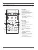
8. P.C.B Diagrams ( This Document can not be used without Samsung’s authorization ) 8-1 P.C.B Diagrams 1 LV T 1 S LV -5574U R 11 2K F1 R 12 20K F2 R 01 -24V UZ5.
8-2 P.C.B Parts List (S.N.A : SERVICE NOT AVAILABLE) LEVEL Code No. Description 1-1 0204-001118 FLUX 1-2 0401-001002 1-2 1-2 1-2 1-2 Specification Q’ty SA/ SNA SV-95-1F,C19H29COOH,C3H7OH,-,1 1 SNA DIODE-SWITCHING 1N4148M,100V,200mA,DO-34,TP 23 SNA D04~D14,D16~D24, D26~D28 0402-001103 DIODE-RECTIFIER 1T4,400V,1A,SOD-106,TP 5 SNA D01~D03,D15,D25 0403-000355 DIODE-ZENER UZ5.1BSB,5-5.2V,500MW,DO-35,TP 4 SNA ZD01,ZD03~ZD05 0504-001044 TR-DIGITAL KRA226M,PNP,400MW,2.
8-2 P.C.B Parts List(continued) (S.N.A : SERVICE NOT AVAILABLE) LEVEL Code No. Description 1-1 3711-000879 CONNECTOR-HEADER 1-1 3711-000999 CONNECTOR-HEADER 1-1 3711-004200 CONNECTOR-HEADER Specification Q’ty SA/ SNA BOX,3P,1R,2.5mm,STRAIGHT,SN 1 SNA CN05 BOX,5P,1R,2.5mm,STRAIGHT,SN 1 SNA CN02 BOX,4P/7P,1R,2.5MM,STRAIGHT,SN,RED 1 SNA CN03 Remark 1-1 3711-004201 CONNECTOR-HEADER BOX,6P/9P,1R,2.
9.
10.
10-2 Customer inquiry cases and countermeasures Symptom Cause Countermeasures Air is evacuated from the oven. • The vent of the oven is designed to be placed on the bottom of the product, and air is evacuated from the oven. In the past, the vent was placed on the back panel of the oven. Since the oven was placed near the wall of a kitchen, the wall behind the oven was discolored. Thus, the vent of a new oven is placed on the bottom of the product, and air is evacuated from the oven.
10-2 Customer inquiry cases and countermeasures (Continued) Symptom Cause Countermeasures Strange popping sounds are produced while fish is cooked. • Since fish is salty and maintains its moisture, it is cooked while making a series of soft popping sounds. (The liquid may come out of the fish when the fish is cooked.) • Food with bones such as fish (e.g. mackerel) and pork (e.g. pork chops) is cooked while making a series of soft popping sounds.
This Service Manual is a property of Samsung Electronics Co.,Ltd. Any unauthorized use of Manual can be punished under applicable International and/or domestic law. © Samsung Electronics Co., Ltd. June 2005 Printed in Korea Code No.