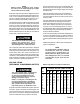
General Operation and Parts Instructions for Gasoline Compressor Outfits MODEL NO. DACE-7161-2 ENGINE HORSE POWER 11HP COMPRESSOR BORE 1.96/4.3 COMPRESSOR STROKE 2.17 AIR TANK CAPACITY 30 GAL. APPROXIMATE UNLOADER PRESSURE 175 PSIG SCFM @ 100 psig 12.5 SCFM @ 175 Psig 12.0 • This product is not equipped with a spark arresting muffler.
TABLE OF CONTENTS Page No. SAFETY PRECAUTIONS ................................................................................... 3-5 GENERAL INFORMATION .................................................................................... 6 COMPRESSOR DIAGRAM ................................................................................... 7 DESCRIPTION OF OPERATION ......................................................................... 6 INSTALLATION ....................................................
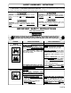
SAFETY GUIDELINES - DEFINITIONS This manual contains information that is important for you to know and understand. This information relates to protecting YOUR SAFETY and PREVENTING EQUIPMENT PROBLEMS. To help you recognize this information, we use the symbols to the right. Please read the manual and pay attention to these sections. DANGER indicates an imminently hazardous situation which, if not avoided, will result in death or serious injury.
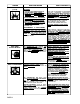
HAZARD RISK OF BURSTING (cont’d) WHAT CAN HAPPEN HOW TO PREVENT IT AIR TANK 3. UNAUTHORIZED MODIFICATIONS TO THE UNLOADER VALVE, SAFETY VALVE, OR ANY OTHER COMPONENTS WHICH CONTROL TANK PRESSURE. THE TANK IS DESIGNED TO WITHSTAND SPECIFIC OPERATING PRESSURES. NEVER MAKE ADJUSTMENTS OR PARTS SUBSTITUTIONS TO ALTER THE FACTORY SET OPERATING PRESSURES. 4. EXCESSIVE VIBRATION CAN WEAKEN THE AIR TANK AND CAUSE RUPTURE OR EXPLOSION.
HAZARD RISK FROM MOVING PARTS WHAT CAN HAPPEN THE ENGINE CAN START ACCIDENTALLY IF THE FLYWHEEL IS TURNED BY HAND OR MOVED BY PULLING ON THE STARTER ROPE. ALWAYS DISCONNECT THE SPARK PLUG AND BLEED PRESSURE FROM THE TANK BEFORE PERFORMING MAINTENANCE. MOVING PARTS SUCH AS THE PULLEY, FLYWHEEL AND BELT CAN CAUSE SERIOUS INJURY IF THEY COME INTO CONTACT WITH YOU OR YOUR CLOTHING. NEVER OPERATE THE COMPRESSOR WITH GUARDS OR COVERS WHICH ARE DAMAGED OR REMOVED.
GENERAL INFORMATION You have purchased a complete compressor outfit consisting of an air compressor, ASME approved air tank, gasoline engine, and associated controls and instruments. The compressor outfit you have selected is a two stage stationary outfit. Your new compressor can be used for operating paint sprayers, air tools, grease guns, air brushes, caulking guns, and sand blasters, spraying weed killer and insecticides, etc. An air pressure regulator may be necessary for some of these applications.
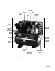
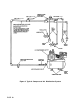
Gas Engine Pump Air Intake Filter Engine Oil Dipstick Fuel Tank Belt Guard Two-Stage Pump Engine Air Filter Pump Oil Fill Plug Engine Oil Drain (Not Shown) Throttle Control Pump Oil Sight Glass Unloader Pump Oil Drain Plug Safety Valve Pressure Gauge Drain Valve (Not Shown) Air Outlet For Discharge Valve Figure 1 - Typical Gasoline Compressor Outfit PAGE 7
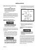
INSTALLATION PRE-INSTALLATION INSPECTION NOTE Each air compressor outfit is carefully checked before shipment. With improper handling, damage may result in transit and cause problems in compressor operation; a bent crankshaft, etc. 2. Insert the vibration mounts in the mounting holes. Place a flat washer under the mounting surface and secure each mount with a lockwasher and nut. See Figure 3.
NOTE Where a remote air intake is used, enlarge the side of the air intake piping by one pipe size for each 10 feet of length. Pipe thread sealant must be used on all threads, and all joints are to be made up tight, since small leaks in the piping system are the largest single cause of high operating costs. Stationary outfits must be bolted or lagged to the floor to prevent movement. When lagging down, leave a minimum of 1/8 inch between the bolt and support feet.
Figure 4.
OPERATION Operator Controls The unloader valve for the operation of the gasoline compressor outfit is located between the compressor pump and gasoline engine. The air discharge valve can be located on the end of the air tank. The safety valve and pressure gauge are attached to the tank below the unloader. See page 7. Unloader Valve Pressure loads beyond the design limits may cause tank rupture or explosion.
The unloader then reactivates the throttle control and accelerates the engine to full throttle. Over-pressurization of the air tank may cause tank rupture or explosion. The air tank is protected from overpressurization by a safety valve. Do not eliminate, make adjustments or substitutions to this device. Occasionally pull the ring on the safety valve to make sure it operates freely. If it doesn’t, the safety valve must be replaced.
3. Periodically check the compressor outfit during the first few days of operation to make sure the compressor outfit is running smoothly and all controls are operating properly. NOTE After the compressor has been in operation for 2 to 3 hours, tighten the compressor head bolts. Torque two stage compressor head bolts to 35 foot-pounds using a crisscross pattern when tightening. BREAK-IN PROCEDURES Perform steps 1-8 of the Daily Startup Procedures. Open the air discharge valve.
c. Check for excessive vibration and noise. Correct any defects found. 2. Turn the engine lever or key switch to the OFF position. d. 3. Close the air discharge valve. Check for oil leaks. Correct any leaks found. 4. Remove air tool or accessory. SHUT DOWN PROCEDURES To stop the engine in an emergency, turn the engine ON/OFF lever or key switch to the OFF position. Under normal conditions, use the following procedures. 5. Open outlet valve or regulator to allow air to slowly bleed from the tank.
WEEKLY 1. Clean and inspect the compressor air intake filter; replace if necessary. 2. Inspect condition of drive belt; replace if necessary. 3. Clean outside parts of the compressor as well as the engine in order to maintain efficient cooling. MONTHLY CLEANING THE AIR COMPRESSOR OUTFIT The external components of the compressor outfit should be cleaned at least once a week. The air compressor crankcase and head are designed with fins which allow for proper cooling.
CHECKING AND CHANGING AIR INTAKE FILTER NOTE Keep the air filter clean at all times. Do not operate compressor outfit when the filters are removed. The condition of the air intake filter should be checked once a week. A dirty air intake filter will not allow the compressor to operate at full capacity and will increase oil usage. When the air filter becomes dirty, oily, or covered with paint overspray it must be replaced.
4. Hold the belt tension until the engine mounting hardware can be tightened. 5. Ensure that the belts are centered on the engine pulley and compressor flywheel. NOTE Once the engine has been moved from its factory set location the engine pulley must align to within 1/16 inch to the compressor flywheel. Figure 8. Checking Belt Tension 6. Torque engine mounting bolts to 20 +3 foot pounds. 7. Reinstall the belt guard. 8. Connect the spark plug wire.
REPLACING DRIVE BELT (cont’d) 6. Reinstall the drive belt. Make sure the belt is centered on the engine pulley and flywheel. 5. Slide the engine back into its original position and adjust the belt tension, Figure 8. 7. Slide the engine back into its original position and adjust the belt tension, Figure 8.
6. Reinstall the check valve. DO NOT OVERTIGHTEN. SERVICING INTAKE AND EXHAUST VALVES The intake and exhaust valves as well as the valve plates and cylinder head will, over a period of time accumulate residue of carbon-like material on their surfaces. The material will decrease the efficiency of the compressor. These components should be inspected, whenever a problem is suspected, and cleaned or replaced with new parts. Use the following procedure to inspect the parts.
TROUBLESHOOTING GUIDE Performing service checks or repairs may expose moving parts, or compressed air sources. Personal injuries may occur. Prior to attempting any service check or repairs, remove the spark plug wire and bleed off all air pressure. Never operate the outfit with the belt guard removed. Repairs should be preformed by an Authorized Service Center personnel only. TROUBLESHOOTING CHART PROBLEM Gasoline Engine will not run.
TROUBLESHOOTING CHART (Continued) PROBLEM Rough Operation of Gasoline Engine. (Consult the "Gasoline Engine Owners Manual" for Manufacturer's Service Center for warranty, repairs and service parts.) CAUSE CORRECTION Clogged fuel line. Clean. Water in fuel. Be sure outfit is adequately protected from the elements so as to prevent water seeping into system. Faulty choke control. Adjust. See engine manufacturer's instructions included with engine. Improper fuel mixture.
TROUBLESHOOTING CHART (Continued) CAUSE PROBLEM Air leaks (cont) Low Discharge Pressure Knocking PAGE 22 CORRECTION Air leak in safety valve. Operate safety valve manually by pulling on ring. If valve still leaks, it should be replaced. Defective check valve. (Unloader valve) A defective check valve results in a constant air leak, back through the unloader valve when there is pressure in the air tank and the compressor is not running.
TROUBLESHOOTING CHART (Continued) CAUSE PROBLEM Knocking (cont’d) Excessive Oil Consumption Flywheel loose. Make sure flywheel is tight by tightening screw. Torque screw to 20 +5 -0 foot-pounds. Loose belt. Tighten belt. Restricted air intake. Replace. Compressor overworked. Reduce air consumption or add additional air compressor to take up load. Poor quality or automotive multiviscosity oil used. Compressor Over heating CORRECTION Drain pump and replace with new oil.
TROUBLESHOOTING CHART (Continued) PROBLEM Compressor Overheating (Cont) Excessive Belt Wear CAUSE CORRECTION Restricted air intake. Remove and clean or replace air filter. Improper level and/or grade of oil used. Check for proper oil levels and recommended oil usage. Damaged valves (intake and/or exhaust). Repair or replace as necessary. Loose belt. Adjust belt tension. Pulley misalignment. Align pulley to within 1/16 inch of the flywheel. Loose pulley. Check for worn key or pulley bore.
COMPRESSOR/PUMP DIAGRAM AND PARTS LIST PAGE 25
Air Compressor Diagram Detail A 29 31 3 30 19 11 21 22 28 23 24 25 27 26 38 1 11 2 13 14 34 5 7 3 6 36 33 4 32 8 35 13 14 12 11 PAGE 26 18
Parts List KEY NO.
Compressor Pump Diagram PAGE 28
Parts List KEY NO. 1 2 3 4 5 6 7 8 9 10 11 12 13 •14 15 16 •17 PARTS NUMBER ABP-8226501 ABP-5961405 ABP-5940055 ABP-5950057 ABP-5281100 ABP-5981000 ABP-9024011 ABP-9022003 ABP-9013013 ABP-9004009 ABP-9110022 ABP-5000101 ABP-5962020 ABP-8226502 ABP-8227093 ABP-8227092 ABP-8226503 DESCRIPTION Hardware Kit Head Valve Plate Kit Gasket Kit Filter Filter Assy.
LIMITED WARRANTY ONE YEAR FROM DATE OF PURCHASE All merchandise manufactured by DeVilbiss Air Power Company/ExCell Manufacturing is warranted to be free of defects in workmanship and material which occur during the first year from the date of purchase by the original purchaser (initial user). Products covered under this warranty include: air compressors, *air tools, accessories, service parts, pressure washers, and generators used in consumer applications (i.e., personal residential household usage only).
Service Notes PAGE 31
GENERAL OPERATION AND PARTS FOR GASOLINE COMPRESSOR OUTFITS MODEL NO. DACE-7161-2 Call our Toll Free Number 1-800-888-2468, Ext 2, then 1, to obtain the location of the nearest Authorized Service Center for ordering repair parts and for warranty repairs. When ordering repair parts from your local Authorized Service Center, always give the following information: • Model number of your product • Part number and description of the item you wish to purchase WARRANTY Attach Sales Receipt Here.