OWNERS MANUAL FOR TWO-STAGE AIR COMPRESSOR Model No. LN1080H23M-1 Specification Chart Model No. LN1080H23M-1 Horsepower 10 Voltage/Hertz/Phase 208/230/460/60 HZ/3 PHASE Minimum Branch Circuit Requirement 30 Amp *Fuse Type Fusetron Type "T" Air Tank Capacity 80 Gal. ASME Approximate Cut-in Pressure 140 PSIG Approximate Cut-out Pressure 175 PSIG SCFM @ 175 PSIG 34.2 Magnetic Starter Required (Included on Compressor) *A circuit breaker is preferred.
TABLE OF CONTENTS Page Page SAFETY GUIDELINES .................................. 2 MAINTENANCE ............................................. 13 SPECIFICATIONS ......................................... 5 GLOSSARY ................................................... 5 DUTY CYCLE ................................................ 5 GENERAL INFORMATION ........................... 6 SERVICE INSTRUCTIONS ............................ 14-17 Air Filter-Inspection and Replacement ........
IMPORTANT SAFETY INSTRUCTIONS SAVE THESE INSTRUCTIONS IMPROPER OPERATION OR MAINTENANCE OF THIS PRODUCT COULD RESULT IN SERIOUS INJURY AND PROPERTY DAMAGE. READ AND UNDERSTAND ALL WARNINGS AND OPERATING INSTRUCTIONS BEFORE USING THIS EQUIPMENT. HAZARD RISK OF EXPLOSION OR FIRE WHAT CAN HAPPEN HOW TO PREVENT IT IT IS NORMAL FOR ELECTRICAL CONTACTS WITHIN THE MOTOR AND PRESSURE SWITCH TO SPARK.
HAZARD RISK FROM FLYING OBJECTS WHAT CAN HAPPEN HOW TO PREVENT IT THE COMPRESSED AIR STREAM CAN CAUSE SOFT TISSUE DAMAGE TO EXPOSED SKIN AND CAN PROPEL DIRT, CHIPS, LOOSE PARTICLES AND SMALL OBJECTS AT HIGH SPEED, RESULTING IN PROPERTY DAMAGE OR PERSONAL INJURY. ALWAYS WEAR ANSI Z87.1 APPROVED SAFETY GLASSES WITH SIDE SHIELDS WHEN USING THE COMPRESSOR. NEVER POINT ANY NOZZLE OR SPRAYER TOWARD ANY PART OF THE BODY OR AT OTHER PEOPLE OR ANIMALS.
HAZARD RISK FROM MOVING PARTS WHAT CAN HAPPEN HOW TO PREVENT IT MOVING PARTS SUCH AS THE PULLEY, FLYWHEEL AND BELT CAN CAUSE SERIOUS INJURY IF THEY COME INTO CONTACT WITH YOU OR YOUR CLOTHING. NEVER OPERATE THE COMPRESSOR WITH GUARDS OR COVERS WHICH ARE DAMAGED OR REMOVED. ATTEMPTING TO OPERATE COMPRESSOR WITH DAMAGED OR MISSING PARTS OR ATTEMPTING TO REPAIR COMPRESSOR WITH PROTECTIVE SHROUDS REMOVED CAN EXPOSE YOU TO MOVING PARTS AND CAN RESULT IN SERIOUS INJURY.
SPECIFICATIONS Refer to cover page for the specifications of your compressor. Use only a fuse or circuit breaker that is the same rating as the branch circuit the air compressor is operated on. If the compressor is connected to a circuit protected by fuses, use dual element time delay fuses, as noted in specification chart. Improper electrical installation of this product may void its warranty and your fire insurance.
GENERAL INFORMATION You have purchased a complete compressor outfit consisting of an air compressor, air tank, electric motor, and associated controls and instruments. The outfit you have selected is a stationary model and contains a two stage air compressor pump. Your new compressor outfit can be used for operating paint sprayers, air tools, grease guns, air brushes, caulking guns, sandblasters, inflating tires, etc. of air regulation and/or moisture and dirt removal should be used where applicable.
DESCRIPTION OF OPERATION Drain Valve: At the base of the air tank to drain condensation at the end of each use. ON/AUTO-OFF Switch: Turn this switch ON to provide automatic power to the pressure switch and OFF to remove power. Air Intake Filter: This filter is designed to clean air coming into the pump. This filter must always be clean and ventilation openings free from obstructions. See "Maintenance".
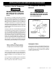
INSTALLATION AND BREAK-IN PROCEDURES Location of the Air Compressor Air Compressor Anchoring Methods THE PUMP ASSEMBLY DOES NOT PROVIDE ADEQUATE STABILITY OR SUPPORT FOR LIFTING THE UNIT. IF THE OUTFIT MUST BE MOVED, USE THE TANK FOR LIFTING. VIBRATION CAN WEAKEN THE AIR TANK AND CAUSE AN EXPLOSION. THE COMPRESSOR MUST BE PROPERLY MOUNTED AS ILLUSTRATED BELOW. This compressor should be permanently mounted in place on a level floor. Operate the air compressor in a clean, dry and well ventilated area.
INSTALLATION AND BREAK-IN PROCEDURES Wiring Instructions If your compressor unit is not equipped with a plug-in type power cord, perform electrical wiring according to the following instructions: IMPROPER ELECTRICAL GROUNDING CAN RESULT IN A RISK OF ELECTRICAL SHOCK. WIRING SHOULD BE DONE BY A LICENSED ELECTRICIAN IN ACCORDANCE WITH NATIONAL AND LOCAL CODES AND ORDINANCES. Install the compressor outfit as close to the main power supply as possible.
INSTALLATION AND BREAK-IN PROCEDURES Air Filter Installation To install air filter: Insert threaded end of the air filter assembly into elbow and tighten until snug. Do not operate compressor without air filter assembly installed as this will cause damage to the compressor. Outlet Valve Installation Insert threaded end of the outlet valve into the tank and tighten until snug. Break-In Procedures Serious damage may result if the following break-in instructions are not closely followed.
INSTALLATION AND BREAK-IN PROCEDURES Piping Plastic or PVC pipe is not designed for use with compressed air. Regardless of its indicated pressure rating, plastic pipe can burst from air pressure. Use only metal pipe for air distribution lines. Note Where a remote air intake is used, enlarge the size of the air intake piping by one pipe size for each 10 feet of length.
OPERATING PROCEDURES 1. Before attaching an air hose or accessory, make sure the outlet valve is in the closed position. On units equipped with a pressure switch lever make sure the switch is in the OFF position. Compressed air from the outfit may contain water condensation and oil mist. Do not spray unfiltered air at an item that could be damaged by moisture or oil mist. Some air operated tools or devices may require filtered air. Read instructions for air tool or device. 2.
MAINTENANCE UNIT CYCLES AUTOMATICALLY WHEN POWER IS ON. DURING MAINTENANCE, YOU COULD BE EXPOSED TO VOLTAGE SOURCES, COMPRESSED AIR OR MOVING PARTS. PERSONAL INJURIES CAN OCCUR. DISCONNECT POWER SOURCE AND BLEED OFF ALL AIR TANK PRESSURE BEFORE DOING ANY MAINTENANCE OR REPAIR. NEVER OPERATE THE UNIT WITH THE BELT GUARD REMOVED. To ensure efficient operation and longer life of the air compressor outfit, a routine maintenance schedule should be prepared and followed.
SERVICE INSTRUCTIONS Air Filter - Inspection and Replacement NOTE Keep the air filter clean at all times. Do not operate the compressor with the air filter removed. A dirty air filter will not allow the compressor to operate at full capacity. Before you use the compressor, check the air filter to be sure it is clean. If it is dirty, replace it with a new filter. Oil - Checking and Changing Overfilling with oil will cause premature compressor failure. Do not overfill. 1.
SERVICE INSTRUCTIONS 6. Check that the valve disc moves freely and that the spring holds the disc in the upper, closed position. The check valve may be cleaned with a solvent. 7. Apply sealant to the check valve threads. Reinstall the check valve. Do not overtighten. 8. Replace the outlet tube and tighten top and bottom nuts. Do not overtighten. 9. Replace the pressure release tube and tighten nuts. Do not overtighten.
SERVICE INSTRUCTIONS Adjusting Belt Tension Adjust belt tension as described below. For compressors with a motor slide mount, adjust belt tension as follows: 1. Slide motor away from compressor until desired tension is obtained. Motor Pulley and Flywheel Alignment 1. Remove outer beltguard - To remove, loosen and remove beltguard screws located at top of beltguard. Insert a flat bladed screwdriver and pry beltguard apart. 2.
SERVICE INSTRUCTIONS Additional Service Disassembly or service of the air compressor beyond what is covered in this manual is not recommended. If additional service is required, contact your nearest Authorized Warranty Service Center. STORAGE OF COMPRESSOR OUTFIT 1. Review the Maintenance section on the preceding pages and perform scheduled maintenance as necessary. Drain the water from the air tank. 4. Protect the electrical cord and/or air hose from damage (such as being stepped on or run over). 5.
TROUBLESHOOTING GUIDE PERFORMING REPAIRS MAY EXPOSE VOLTAGE SOURCES, MOVING PARTS OR COMPRESSED AIR SOURCES. PERSONAL INJURY MAY OCCUR. PRIOR TO ATTEMPTING ANY REPAIRS, DISCONNECT POWER SOURCE FROM THE COMPRESSOR AND BLEED OFF ALL TANK AIR PRESSURE. PROBLEM CAUSE CORRECTION Excessive tank pressure - safety valve pops off (units with ONAUTO switch) Pressure switch does not shut off motor when compressor reaches “cut-out” pressure. Move the pressure switch lever to the "OFF" position.
TROUBLESHOOTING GUIDE PROBLEM CAUSE CORRECTION Motor will not run. Motor overload protection switch has tripped. Let motor cool off for 10-15 minutes and overload protection switch will reset automatically. If the overload still trips, check for defective capacitor. Tank pressure exceeds pressure switch "cut-in pressure". Motor will start automatically when tank pressure drops below "cut-in pressure" of pressure switch. Check valve stuck open. Remove and clean or replace. DO NOT OVERTIGHTEN.
TROUBLESHOOTING GUIDE PROBLEM Compressor is not supplying enough air to operate accessories. (Continued) Knocking noise. Excessive oil consumption. Compressor overheating. Motor overheating. CAUSE CORRECTION Loose belt. Adjust belt tension. Hole in hose. Check and replace if required. Check valve restricted. Remove and clean or replace. Air leaks. Tighten fittings. (See "Air Leaks" section of "Troubleshooting Guide".) Defective check valve. Remove and clean or replace. Loose pulley.
TROUBLESHOOTING GUIDE PROBLEM CAUSE CORRECTION Motor overheating. (Continued) Too many motor starts per hour. Consult Service Center. Improper wiring gauge. Incorrect voltage. Check electrical hookup and installation data or consult electrician. NOTE Current style electric motors run relatively hot under normal operating conditions, with reasonable compressor loading. This condition is normal and no adjustment is necessary.
COMPRESSOR DIAGRAM 52, 53 TORQUE 35-50 IN.-LB. 38 39 21,42 PRESSURE SWITCH WIRING 44 36 35 20 REFERENCE REFERENCE No. 1 No. 8 19 46 17 18 41 REFERENCE No. 10 9 45 22 15 16 51 1 TORQUE 145-165 IN.-LB. 24 47,48 TORQUE 33-37 FT.-LB. LEFT HAND THREADS 5 9 7 26 25 8 10 11 TORQUE 20-25 FT.-LB. 6 2 37 4 TORQUE 80-90 IN.-LB. 56 23—ENG MGP-LN1080H2-1A Rev.
COMPRESSOR PARTS LIST Key Part No.
COMPRESSOR PUMP DIAGRAM 25—ENG MGP-LN1080H2-1A Rev.
PUMP PARTS LIST MGP-LN1080H2-1A Rev. 1 Key No.
LIMITED WARRANTY All merchandise manufactured by DeVilbiss Air Power Company Manufacturing is warranted to be free of defects in workmanship and material which occur during the first year from the date of purchase by the original purchaser (initial user). Products covered under this warranty include: air compressors, *air tools, accessories, service parts, pressure washers, and generators used in consumer applications (i.e., personal residential household usage only).
OWNERS MANUAL FOR TWO-STAGE AIR COMPRESSOR Model No. LN1080H23M-1 Call our Toll Free Number 1-800-888-2468, Ext 2, then 1 to obtain the location of the nearest Authorized Service Center for ordering repair parts and for warranty repairs.