
Electric Generator Operator's Manual

10- ENG
A04669
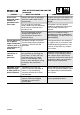
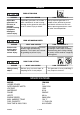
OPERATION
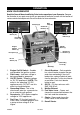
1. Engine On/Off Switch - Enables
and disables the ignition system.
2. Pilot Lamp - Indicates voltage is
being provided by generator.
3. 12V DC Outlet - Supplies voltage
to 12V DC appliances. NOTE: This
outlet is for operating 12V DC
appliances only, DO NOT use this
outlet to charge batteries.
4. Grounding Screw- This is the
attachment point for a ground wire
to an external earth ground.
5. Receptacle- 120V duplex supplies
voltage to 120V appliances.
6. Fuel Cap - Fill the fuel tank with
clean, fresh, unleaded gasoline with
a pump octane rating of 87 or
higher.
7. Circuit Breakers -
Each receptacle
has a circuit breaker to protect the gen-
erator from overloading. If the circuit
breaker trips, unplug all electrical loads
from the generator. Let the circuit break-
er cool down. Push circuit breaker
button to reset.
8. Oil Fill - Fill the crankcase with
SAE 10W-30 oil.
9. Muffler Exhaust
10. Fuel Valve Lever - Opens and
closes the connection between the
fuel tank and the carburetor.
11. Choke- Opens and closes the
choke valve in the carburetor.
12. Recoil Starter
KNOW YOUR GENERATOR
Read this General Manual and Safety Rules before operation of your Generator. Compare
the illustration in your parts manual with your generator to familiarize yourself with the location of
various controls and adjustments. Save all manuals for future references.
Muffler
Exhaust (9)
Choke (11)
Fuel Valve
Lever (10)
Oil Fill (8)
12V DC
Outlet (3)
DC Circuit
Breaker (7)
Grounding
Screw (4)
Pilot
Lamp (2)
Engine
On/Off
Switch (1)
Receptacle (5)
AC Circuit
Breakers (7)
Fuel Cap (6)
Recoil
Starter (12)