
Product Overview


TECHNICAL GUIDE – MECHANICAL ANCHORS ©2021 DEWALT – REV. C
A
NCHORS & FASTENERS
PERFORMANCE DATA
4
Mechanical anchors
PERFORMANCE DATA
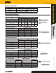
Ultimate and Allowable Load Capacities for Carbon and Stainless
Steel Lok-Bolt AS Anchors in Normal Weight Concrete
1,2,3,4
Nominal
Anchor
Diameter
d
in.
Min.
Embed.
Depth
h
v
in.
Guide Installation
Torque
ft.-lbs.
Minimum Concrete Compressive Strength, f’c
3,000 psi 3,500 psi 4,000 psi
Carbon Stainless
Ultimate Allowable Ultimate Allowable Ultimate Allowable
Tension
lbs.
Shear
lbs.
Tension
lbs.
Shear
lbs.
Tension
lbs.
Shear
lbs.
Tension
lbs.
Shear
lbs.
Tension
lbs.
Shear
lbs.
Tension
lbs.
Shear
lbs.
1/4
1/2 2 - 225 1,000 55 250 240 1,000 60 250 260 1,000 65 250
1 6 4 910 1,120 230 280 980 1,120 245 280 1,050 1,120 265 280
5/16 1 12 - 1,205 2,360 300 590 1,300 2,360 325 590 1,390 2,360 350 590
3/8 1-1/4 18 18 1,875 4,110 470 1,030 2,040 4,110 510 1,030 2,165 4,110 540 1,030
1/2 1-1/2 26 26 2,235 4,860 560 1,215 2,420 4,860 605 1,215 2,580 4,860 645 1,215
5/8 2 50 40 4,870 4,860 1,220 1,215 5,260 4,860 1,315 1,215 5,625 4,860 1,405 1,215
3/4 2-1/4 90 60 5,045 11,040 1,260 2,760 5,450 11,040 1,365 2,760 5,825 11,040 1,455 2,760
1. The ultimate load values listed above must be reduced by a minimum safety factor of 4.0 or greater to determine the allowable working load. Consideration of safety factors of 10 or higher
may be necessary depending on the application, such as life safety or overhead.
2. Allowable load capacities listed are calculated using an applied safety factor of 4.0. Consideration of safety factors of 10 or higher may be necessary depending on the application, such as life
safety or overhead.
3. Tabulated load values are for anchors installed at a minimum spacing distance between anchors and an edge distance of 12 times the anchor diameters.
4. The embedment depth is measured from the outside surface of the concrete member to the embedded end of the anchor prior to tightening.
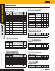
Ultimate and Allowable Load Capacities for Carbon and Stainless Steel
Lok-Bolt AS Anchors in Hollow or Solid Concrete Masonry
1,2,3,4,5,6
Nominal
Anchor
Diameter
d
in.
Minimum
Embed.
Depth
h
v
in.
Guide
Installation
Torque
ft.-lbs.
Minimum
Edge Dist.
in.
Minimum
End Dist.
in.
Ultimate Loads Allowable Loads
Tension
lbs.
Shear
lbs.
Tension
lbs.
Shear
lbs.
1/4 1 4
3-3/4 4
800 1,140 160 225
5/16 1 8 905 1,570 180 310
3/8 1-1/4 15 1,100 1,570 220 310
1/2 1-1/2 18 1,525 1,570 305 310
5/8 1-1/2 30 2,250 1,770 450 355
1. Tabulated load values are for anchors installed in minimum 6 inch wide, Grade N, Type II, normal-weight concrete masonry units conforming to ASTM C 90. Mortar must be minimum Type N,
S, or M. Masonry prism compressive strength must be 1,500 psi minimum at time of installation.
2. Allowable load capacities listed are calculated using an applied safety factor of 5.0. Consideration of safety factors of 10 or higher may be necessary depending on the application, such as life
safety or overhead.
3. A suitable anchor length must be selected which includes consideration of a fixture to engage the base material at the minimum embedment depth when anchoring into hollow concrete
masonry. (e.g. attachment thickness + face shell thickness embedment + one half inch = suitable anchor length)
4. The consistence of hollow concrete block masonry base material can vary greatly. Consideration of job site testing should be given to verify conformance of base materials and anchor
performance in actual conditions.
5. Tabulated load values are for anchors installed at a minimum spacing distance between anchors and an edge distance of 16 times the anchor diameters.
6. The embedment depth is measured from the outside surface of the masonry member to the embedded end of the anchor prior to tightening.
Ultimate and Allowable Load Capacties for Carbon or Stainless Steel Lok-Bolt AS Anchors in
Solid Clay Brick Masonry
1,2,3,4
Nominal
Anchor
Diameter
d
in.
Minimum
Embed.
Depth
h
v
in.
Guide
Installation
Torque
ft.-lbs.
Minimum Edge
Dist.
in.
Minimum
End Dist.
in.
f’m ≥ 1,500 psi (10.4 MPa)
Ultimate Allowable
Tension
lbs.
Shear
lbs.
Tension
lbs.
Shear
lbs.
1/4 1 4 4 1-1/2 800 950 160 190
3/8 1-1/4 15 8 8 1,100 3,000 220 600
1/2 1-1/2 26 8 8 1,560 3,150 310 630
5/8 2 40 8 8 2,470 5,250 495 1,050
1. Tabulated load values are for anchors installed in Grade SW, multiple wythe solid clay brick masonry conforming to ASTM C 62.
2. Allowable load capacities listed are calculated using a safety factor of 5.0 or greater. Consideration of safety factors of 10 or higher may be necessary depending on the application,
such as life safety or overhead.
3. Tabulated load values are for anchors installed at a minimum spacing distance between anchors and an edge distance of 16 times the anchor diameters.
4. The embedment depth is measured from the outside surface of the brick masonry member to the embedded end of the anchor prior to tightening.