
Cut Sheet


www.powers.com
3
TECH MANUAL – MECHANICAL ANCHORS ©2015 POWERS – REV. G
DESIGN CRITERIA (ALLOWABLE STRESS DESIGN)
Mechanical anchors
Ultimate and Allowable Load Capacities for Mini Dropin in Precast Hollow Core Concrete Plank
1,2
Rod/
Anchor
Size
d
in.
(mm)
Minimum
Embed.
Depth
h
v
in.
(mm)
Minimum
Spacing
in.
(mm)
Minimum
Edge
Distance
in.
(mm)
Min. Concrete Compressive Strength
f´c ≥ 5,000 psi (34.5 MPa)
Ultimate Load Allowable Load
Tension
lbs.
(kN)
Shear
lbs.
(kN)
Tension
lbs.
(kN)
Shear
lbs.
(kN)
1/4
(6.4)
5/8
(15.9)
3
(76.2)
3
(76.2)
1,400
(6.2)
1,840
(8.3)
350
(1.6)
460
(2.1)
3/8
(9.5)
3/4
(19.1)
4-1/2
(114)
4-1/2
(114)
2,600
(11.7)
3,400
(15.3)
650
(2.9)
850
(3.8)
1/2
(12.7)
1
(25.4)
6
(152.4)
6
(152.4)
2,600
(11.7)
3,540
(15.9)
650
(2.9)
885
(4.0)
1. Tabulatedloadvaluesareforanchorsinstalledinconcrete.Concretecompressivestrengthmustbeatthespecified
minimumatthetimeofinstallation.
2. Allowableloadcapacitieslistedarecalculatedusingandappliedsafetyfactorof4.0.
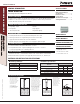
1-1/2"
Mini Dropin (Typ)
design criTeria (allowable sTress design)
Combined Loading
For anchors loaded in both shear and tension, the combination of loads should be proportioned as follows:
N
u
N
n
( )
V
u
V
n
( )
+
≤
1
Where: N
u
= Applied Service Tension Load
N
n
= Allowable Tension Load
V
u
= Applied Service Shear Load
V
n
= Allowable Shear Load
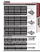
loaD aDjustMent Factors For spacinG anD eDGe Distance
1,2,3
Anchor Installed in Normal-weight Concrete
Anchor Dimension Load Type
Critical Distance
(Full Anchor Capacity)
Critical Load Factor
Minimum Distance
(Reduced Capacity)
Minimum
Load Factor
Spacing (s) Tension and Shear s
cr
= 3.0h
v
F
NC
= F
VC
=1.0 s
min
= 1.5h
v
F
NS
= F
VS
= 0.50
Edge Distance (c)
Tension c
cr
= 12d F
NC
= F
VC
=1.0 c
min
= 6d F
NC
= 0.90
Shear
1
c
cr
= 12d F
NC
= F
VC
= 1.0 c
min
= 6d F
VC
= 0.75
1. AllowableloadsforanchorsloadedinshearparalleltotheedgehavenoloadfactorF
Vc
=1.0wheninstalledatminimumedgedistances.
2. Allowableloadvaluesfoundintheperformancedatatablesaremultipliedbyreductionfactorswhenanchorspacingoredgedistancesarelessthancriticaldistances.Linear
interpolationisallowedforintermediateanchorspacingandedgedistancesbetweencriticalandminimumdistances.Whenananchorisaffectedbybothreducedspacingandedge
distance,thespacingandedgereductionfactorsmustbecombined(multiplied).Multiplereductionfactorsforanchorspacingandedgedistancemayberequireddependingonthe
anchorgroupconfiguration.
Anchor Installed in Through Steel Deck Structural Lightweight Concrete
Anchor Dimension Load Type
Critical Distance
(Full Anchor Capacity)
Critical Load Factor
Minimum Distance
(Reduced Capacity)
Minimum
Load Factor
Spacing (s) Tension and Shear s
cr
= 3.0h
v
F
Ns
= F
Vs
=1.0 s
min
= 1.5h
v
F
NS
= F
vs
= 0.50
3. Allowableloadvaluesfoundintheperformancedatatablesaremultipliedbyreductionfactorswhenanchorspacingislessthancriticaldistances.Linearinterpolationisallowedfor
intermediateanchorspacingbetweencriticalandminimumdistances.Multiplereductionfactorsforanchorspacingmayberequireddependingontheanchorgroupconfiguration.