
Product Overview

10
TECHNICAL GUIDE – ADHESIVES ©2021 DEWALT – REV. F
Adhesives
A
NCHORS & FASTENERS
STRENGTH DESIGN (SD)
STRENGTH DESIGN (SD)
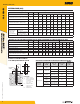
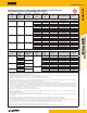
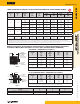
Strength Design Installation Table for AC100+ Gold
1
CODE LISTED
ICC-ES ESR-2582
Parameter Symbol Units
Fractional Nominal Rod Diameter (Inch) / Reinforcing Bar Size
3/8 or #3 1/2 #4 5/8 or #5 3/4 or #6 7/8 or #7 1 or #8 #9 1-1/4 #10
Threaded rod outside diameter d
a
inch
(mm)
0.375
(9.5)
0.500
(12.7)
0.625
(15.9)
0.750
(19.1)
0.875
(22.2)
1.000
(25.4)
-
1.250
(31.8)
-
Rebar nominal outside diameter d
a
inch
(mm)
0.375
(9.5)
0.500
(12.7)
0.625
(15.9)
0.750
(19.1)
0.875
(22.2)
1.000
(25.4)
1.125
(28.7)
-
1.250
(31.8)
Carbide drill bit nominal size d
o
(d
bit
) inch 7/16 9/16 5/8
11/16 or
3/4
7/8 1 1-1/8 1-3/8 1-3/8 1-1/2
Minimum embedment h
ef,min
inch
(mm)
2-3/8
(60)
2-3/4
(70)
3-1/8
(79)
3-1/2
(89)
3-1/2
(89)
4
(102)
4-1/2
(114)
5
(127)
5
(127)
Maximum embedment h
ef,max
inch
(mm)
4-1/2
(114)
6
(152)
7-1/2
(191)
9
(229)
10-1/2
(267)
12
(305)
13-1/2
(343)
15
(381)
15
(381)
Minimum member thickness h
min
inch
(mm)
h
ef
+ 1-1/4
(h
ef
+ 30)
h
ef
+ 2d
o
Minimum anchor spacing s
min
inch
(mm)
1-7/8
(48)
2-1/2
(64)
3-1/8
(79)
3-3/4
(95)
4-3/8
(111)
5
(127)
5-5/8
(143)
6-1/4
(159)
6-1/4
(159)
Minimum edge distance, reduced
5
c
min,red
inch
(mm)
1-3/4
(45)
1-3/4
(45)
1-3/4
(45)
1-3/4
(45)
1-3/4
(45)
1-3/4
(45)
2-3/4
(70)
2-3/4
(70)
2-3/4
(70)
Minimum edge distance c
min
inch
(mm)
1-7/8
(48)
2-1/2
(64)
3-1/8
(79)
3-3/4
(95)
4-3/8
(111)
5
(127)
5-5/8
(143)
6-1/4
(159)
6-1/4
(159)
Max. rod torque
2
T
max
ft-lbs 15 33 60 105 125 165 - 280 -
Max. torque
2,3
(A36/Grade 36 rod)
T
max
ft-lbs 10 25 50 90 125 165 - 280 -
Max. torque
2,4
(Class 1 SS rod)
T
max
ft-lbs 5 20 40 60 100 165 - 280 -
For pound-inch units: 1 mm = 0.03937 inch, 1 N-m = 0.7375 ft-lbf. For SI: 1 inch = 25.4 mm, 1 ft-lbf = 1.356 N-m.
1. For use with the design provisions of ACI 318-14 Ch. 17 or ACI 318-11 Appendix D as applicable and ICC-ES AC308, Section 4.2 and ESR-2582.
2. Torque may not be applied to the anchors until the full cure time of the adhesive has been achieved.
3. These torque values apply to ASTM A 36 / F 1554 Grade 36 carbon steel threaded rods.
4. These torque values apply to ASTM A 193 Grade B8/B8M (Class 1) stainless steel threaded rods.
5. For installation between the minimum edge distance, c
min
, and the reduced minimum edge distance, c
min,red
, the maximum torque must be reduced (multiplied) by a factor of 0.45.
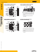
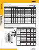
Detail of Steel Hardware Elements
used with Injection Adhesive System
T
max
h
ef
h
c
c
s
d
d
o
(d
bit
)
Threaded Rod
or Rebar
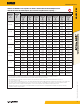
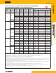
Threaded Rod and Deformed Reinforcing Bar Material Properties
Steel
Description
(General)
Steel Specification
(ASTM)
Nominal Anchor
Size (inch)
Minimum
Yield
Strength, f
y
(ksi)
Minimum
Ultimate
Strength,
f
u
(ksi)
Carbon rod
ASTM A 36 and
F 1554 Grade 36
3/8 through 1-1/4 36.0 58.0
ASTM F 1554 Grade 55 3/8 through 1-1/4 55.0 75.0
ASTM A 449
3/8 through 1 92.0 120.0
1-1/4 81.0 105.0
High Strength
Carbon rod
ASTM A 193
Grade B7 and
F 1554 Grade 105
3/8 through 1-1/4 105.0 125.0
Stainless rod
(Alloy 304/316)
ASTM F 593 Condition CW
3/8 through 5/8 65.0 100.0
3/4 through 1-1/4 45.0 85.0
ASTM A 193 Grade B8/B8M,
Class 1
3/8 through 1-1/4 30.0 75.0
ASTM A 193 Grade B8/B8M2,
Class 2B
3/8 through 1-1/4 75.0 95.0
Reinforcing Bar
ASTM A 615, A 767, Grade 75
3/8 through 1-1/4
(#3 through #10)
75.0 100.0
ASTM A 615, A 767, Grade 60
3/8 through 1-1/4
(#3 through #10)
60.0 90.0
ASTM A 706, A 767, Grade 60
3/8 through 1-1/4
(#3 through #10)
60.0 80.0
ASTM A 615, A 767, Grade 40
3/8 through 1-1/4
(#3 through #10)
40.0 60.0