
Product Overview

2
TECHNICAL GUIDE – ADHESIVES ©2021 DEWALT – REV. F
Adhesives
A
NCHORS & FASTENERS
REFERENCE DATA (ASD)
REFERENCE DATA (ASD)
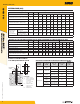
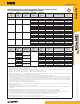
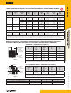
Allowable Stress Design (ASD) Installation Table for AC100+ Gold (Solid Concrete Base Materials)
Dimension/Property Notation Units Nominal Anchor Size
Nominal threaded rod size - in. 3/8 1/2 5/8 3/4 7/8 1 - 1-1/4 -
Carbide drill bit nominal size (ANSI) for threaded rod d
bit
in. 7/16 9/16
11/16
or 3/4
7/8 1 1-1/8 - 1-3/8 -
Reinforcing bar size - No. 3 4 5 6 7 8 9 - 10
Carbide drill bit nominal size (ANSI) for rebar d
bit
in. 7/16 1/2 3/4 7/8 1 1-1/8 1-1/4 1-3/8 1-1/2
Nominal anchor/rebar diameter d
in.
(mm)
0.375
(9.5)
0.500
(12.7)
0.625
(15.9)
0.750
(19.1)
0.875
(22.2)
1.000
(25.4)
1.125
(28.6)
1.250
(31.8)
1.250
(31.8)
Minimum nominal embedment depth h
nom,min
in.
(mm)
2-3/8
(61)
2-3/4
(70)
3-1/8
(79)
3-1/2
(89)
3-1/2
(89)
4
(102)
4-1/2
(114)
5
(127)
5
(127)
Maximum torque
(only possible
after full cure
time of adhesive)
A36 or F1554 Grade 36
carbon steel rod
T
max
ft.-lb.
(N-m)
10
(13)
25
(34)
50
(68)
90
(122)
125
(169)
165
(224)
-
280
(379)
-
F593 Condition CW stainless
steel rod or ASTM A193,
Grade B7 carbon steel rod
T
max
ft.-lb.
(N-m)
16
(22)
33
(45)
60
(81)
105
(142)
125
(169)
165
(224)
-
280
(379)
-
1. The listed drill bit sizes are also applicable to installations into grouted concrete masonry.
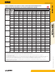
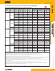
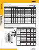
Allowable Stress Design (ASD) Installation Table for AC100+ Gold (Hollow Base Material with Screen Tube)
Dimension/Property Notation Units Nominal Size - Stainless Steel Nominal Size - Plastic
Nominal threaded rod size - in. 1/4 3/8 1/2 5/8 3/4 - 1/4 3/8 1/2 5/8
Nominal anchor diameter d
in.
(mm)
0.250
(6.4)
0.375
(9.5)
0.500
(12.7)
0.625
(15.9)
0.750
(19.1)
-
0.250
(6.4)
0.375
(9.5)
0.500
(12.7)
0.625
(15.9)
Reinforcing bar size
-
No. - - 3 4 5 6 - - - -
Nominal rebar diameter d in. - - 0.375 0.500 0.625 0.750 - - - -
Nominal screen tube diameter - in. 1/4 3/8 1/2 5/8 3/4 15/16 1/4 3/8 1/2 5/8
Carbide drill bit nominal size (ANSI) d
bit
in. 3/8 1/2 5/8 3/4 7/8 1 1/2 9/16 3/4 7/8
Maximum torque, for threaded rods
(only possible after full cure time of adhesive)
T
max
ft.-lbf.
(N-m)
4
(5)
6
(8)
10
(14)
10
(14)
10
(14)
-
4
(5)
6
(8)
10
(14)
10
(14)
For Unreinforced Masonry (URM Walls) see separate installation details and information in this section for 'Retrofit Bolt Anchors in URM Walls'.
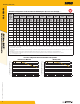
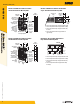
Detail of Steel Hardware Elements
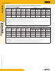
used with Injection Adhesive System Threaded Rod and Deformed Reinforcing Bar Material Properties
T
max
h
nom
h
c
c
s
d
d
o
(d
bit
)
Threaded Rod
or Rebar
Nomenclature
d = Diameter of anchor
d
bit
= Diameter of drilled hole
h = Base material thickness
The greater of:
[h
nom
+ 1-1/4"] and
[h
nom
+ 2d
bit
]
h
nom
= Embedment depth
s = Spacing of anchors
c = Edge distance
T
max
= Maximum torque
Steel
Description
(General)
Steel
Specification
(ASTM)
Nominal
Anchor Size
(inch)
Minimum
Yield Strength,
f
y
(ksi)
Minimum
Ultimate
Strength,
f
u
(ksi)
Carbon Rod
A36 or F1554
Grade 36
3/8 through 1-1/4 36.0 58.0
Stainless Rod
(Alloy 304 / 316)
F593,
Condition CW
3/8 through 5/8 65.0 100.0
3/4 through 1-1/4 45.0 85.0
High Strength
Carbon Rod
A193
Grade B7
3/8 through 1-1/4 105.0 125.0
Reinforcing Bar
A615, A767,
Grade 75
3/8 through 1-1/4
(#3 through #10)
75.0 100.0
A615, A767,
Grade 60
3/8 through 1-1/4
(#3 through #10)
60.0 90.0
A706, A767,
Grade 60
3/8 through 1-1/4
(#3 through #10)
60.0 80.0
A615, A767,
Grade 40
3/8 through 1-1/4
(#3 through #10)
40.0 60.0