
Product Overview

5
Adhesives
TECHNICAL GUIDE – ADHESIVES ©2021 DEWALT – REV. F
A
NCHORS & FASTENERS
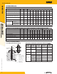
REFERENCE DATA (ASD)
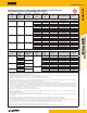
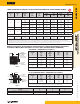
Allowable Load Capacities for Threaded Rod Installed with AC100+ Gold into Grout-Filled
Concrete Masonry (Based on Bond Strength/Masonry Strength)
1,2,3,7,9,12
Anchor
Diameter
d
inch
Minimum
Embedment
h
nom
inch
Critical Spacing
Distance
s
cr
inch
Minimum Edge
Distance
c
min
inch
Minimum End
Distance
c
min
inch
Tension Load
lbs
Direction of Shear Loading
Shear Load
lbs
Anchor Installed Into Grouted Masonry Wall Faces
4,5,6,8,10,11,13
3/8 3 6
3 3 615 Towards Edge/End 275
3 3 615 Away From Edge/End 340
3 4 735 Any 490
12 12 960 Any 855
1/2 4 8
3 3 720 Towards Edge/End 430
3 3 720 Away From Edge/End 1320
4 4 985 Any 655
12 12 960 Towards Edge/End 1430
12 12 960 Away From Edge/End 1760
7-3/4 (Bed Joint) 3 935 Load To Edge 460
5/8 5 10
3 3 710 Towards Edge/End 460
3 3 710 Away From Edge/End 1410
12 12 1095 Towards Edge/End 1530
12 12 1095 Away From Edge/End 1880
7-3/4 (Bed Joint) 3 1030 Load To Edge 590
3/4 6 12
4 4 755 Towards Edge/End 630
4 4 755 Away From Edge/End 1450
12 12 1160 Towards Edge/End 1570
12 12 1160 Away From Edge/End 1930
7-3/4 (Bed Joint) 4 945 Load To Edge 565
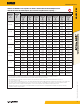
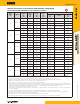
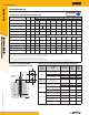
Anchor Installed Into Tops of Grouted Masonry Walls
14,15
Anchor Diameter
d
inch
Minimum
Embedment
h
nom
inch
Minimum Spacing
Distance
Minimum Edge
Distance
c
min
inch
Minimum End
Distance
c
min
inch
Tension Load
lbs
Direction of Shear Loading
Shear Load
lbs
1/2
2-3/4
1 anchor per cell
1-3/4
4 595 Any 300
4 3 520 Load To Edge 190
4 3 520 Load To End 300
10
1 anchor per block
16
10-1/2 1670 Load To Edge 190
10 10-1/2 1670 Load To End 300
5/8
5
1 anchor per cell
3 745 Load To Edge 240
5 3 745 Load To End 300
12-1/2
1 anchor per block
16
1-3/4
10-1/2 2095 Load To Edge 240
12-1/2 10-1/2 2095 Load To End 300
3/4
6
1 anchor per cell
4 1260 Load To Edge 410
6 4 1260 Load To End 490
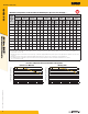
1. Tabulated load values are for anchors installed in nominal 8-inch wide (203 mm) Grade N, Type II, lightweight, medium-weight or normal-weight grout filled concrete masonry units with
a minimum masonry strength, f’m, of 1,500 psi (10.3 MPa) conforming to ASTM C 90. If the specified compressive strength of the masonry, f’m, is 2,000 psi (13.8 MPa) minimum the
tabulated values may be increased by 4 percent (multiplied by 1.04).
2. Allowable bond or masonry strengths in tension and shear are calculated using a safety factor of 5.0 and must be checked against the allowable tension and shear capacities for threaded rod
based on steel strength to determine the controlling factor. See allowable load table based on steel strength.
3. Embedment is measured from the outside surface of the concrete masonry unit to the embedded end of the anchor.
4. Anchors may be installed in the grouted cells, cell webs and bed joints not closer than 1-1/2-inch from the vertical mortar joint (head joint) provided the minimum edge and end distances are
maintained. Anchors may be placed in the head joint if the vertical joint is mortared full-depth.
5. A maximum of two anchors may be installed in a single masonry cell in accordance with the spacing and edge or end distance requirements.
6. The critical spacing, s
cr
, for use with the anchor values shown in this table is 16 anchor diameters. The critical spacing, s
cr
, distance is the distance where the full load values in the table may
be used. The minimum spacing distance, s
min
, is the minimum anchor spacing for which values are available and installation is permitted. For 3/8-inch diameter anchors, the spacing may be
reduced to 8 anchor diameters when using a tension reduction factor of 0.70 and a shear reduction factor of 0.45. For ½ - and 5/8 – inch diameter anchors, the spacing may be reduced to 8
anchor diameters when using a tension reduction factor of 0.85 and a shear reduction factor of 0.45. For 3/4-inch diameter anchors, the spacing may be reduced to 8 anchor diameters when
using a tension reduction factor of 1.00 and a shear reduction factor of 0.45.
7. Spacing distance is measured from the centerline to centerline between two anchors.
8. The critical edge or end distance, c
cr
, is the distance where full load values in the table may be used. The minimum edge or end distance, c
min
, is the minimum distance for which values are
available and installation is permitted.
9. Edge or end distance is measured from anchor centerline to the closest unrestrained edge.
10. Linear interpolation of load values between the minimum spacing, s
min
, and critical spacing, s
cr
, distances and between minimum edge or end distance, c
min
, and critical edge or end distance,
c
cr
, is permitted.
11. The tabulated values are applicable for anchors in the ends of grout-filled concrete masonry units where minimum edge and end distances are maintained.
12. The tabulated values must be adjusted for increased in-service base material temperatures in accordance with the In-Service Temperature chart, as applicable.
13. Concrete masonry width (wall thickness) must be equal to or greater than 1.5 times the anchor embedment depth (e.g. 3/8-inch and 1/2-inch diameter anchors are permitted in nominally
6-inch-thick concrete masonry). The 5/8-inch and 3/4-inch diameter anchors must be installed in minimum nominally 8-inch-thck concrete masonry.
14. Anchors must be installed into the grouted cell; anchors are not permitted to be installed in a head joint, flange or web of the concrete masonry unit.
15. Allowable shear loads parallel or perpendicular to the edge of a masonry wall may be applied in or out of plane.
16. Anchors with minimum spacing distance of one anchor per block may not be installed in adjacent cells (i.e. one cell must separate the anchor locations).