
Product Overview

8
TECHNICAL GUIDE – ADHESIVES ©2021 DEWALT – REV. F
Adhesives
A
NCHORS & FASTENERS
REFERENCE DATA (ASD)
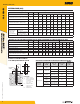
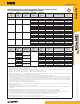
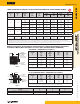
Ultimate and Allowable Load Capacities for AC100+ Gold into Precast Hollow Core Concrete
with Stainless Steel Screen Tubes
1,2,3,4,5,6,7
Anchor
Diameter
d
in.
Drill Bit
Diameter
d
bit
in.
Minimum
Embedment
h
nom
in.
(mm)
Minimum End
Distance
in.
(mm)
Minimum Edge
Distance
in.
(mm)
Ultimate Load Allowable Load
Tension
lbs.
(kN)
Shear
lbs.
(kN)
Tension
lbs.
(kN)
Shear
lbs.
(kN)
1/4 3/8
1-1/2
(38)
4
(102)
4
(102)
900
(4.0)
1,550
(6.9)
180
(0.8)
310
(1.4)
3/8 1/2
1-1/2
(38)
6
(152)
6
(152)
1,975
(8.8)
3,650
(16.2)
395
(1.8)
730
(3.2)
1/2 5/8
1-1/2
(38)
8
(203)
8
(203)
4,400
(19.6)
5,875
(26.1)
880
(3.9)
1,175
(5.2)
1. Tabulated load values are for anchors installed in precast hollow core concrete with minimum strength, f’m, of 5,000 psi (34.5 MPa). Allowable loads have been calculated using a safety
factor of 5.0.
2. Anchors must be installed into the hollow core; anchors are not permitted to be installed in a cell web of the hollow core concrete member.
3. Embedment is measured from the outside surface of the concrete masonry unit to the embedded end of the anchor.
4. Edge or end distance is measured from anchor centerline to the closest unrestrained edge of the concrete member.
5. The tabulated values are for anchors installed at a minimum of 16 anchor diameters on center for 100 percent capacity. Spacing distance is measured from the centerline to centerline
between two anchors.
6. Allowable loads must be the lesser of the adjusted masonry or bond values tabulated above and the steel strength values.
7. The tabulated values must be adjusted for increased in-service base material temperatures in accordance with the In-Service Temperature chart, as applicable.
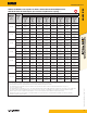
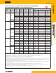
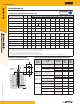
Ultimate and Allowable Load Capacities for Knurled Dropins Installed with AC100+ Gold into Normal Weight Concrete
1,2,3,4,5
Anchor
Diameter
d
in.
Knurled
Dropin
Anchor
Cat. No.
Drill Bit
Diameter
in.
Minimum
Embedment
h
nom
in.
(mm)
Minimum Edge
Distance
in.
(mm)
Ultimate Load Allowable Load
Tension
lbs.
(kN)
Shear
lbs.
(kN)
Tension
lbs.
(kN)
Shear
lbs.
(kN)
1/4 6340 1/2
1
(25)
2
(51)
1,340
(6.0)
1,880
(8.4)
335
(1.5)
470
(2.1)
3/8 6342 5/8
1-9/16
(40)
3
(76)
2,740
(12.2)
3,800
(16.9)
685
(3.0)
950
(4.2)
1/2 6344 3/4
2
(51)
4
(102)
3,160
(14.1)
5,460
(24.3)
790
(3.5)
1,365
(6.1)
1. Allowable load capacities listed are calculated using an applied safety factor of 4.0. Consideration of safety factors of 10 or higher may be necessary depending on the application,
such as life safety.
2. Knurled dropin anchors installed with AC100+ Gold adhesive are not recommended for overhead applications.
3. The tabulated values are for anchors installed at a minimum of 16 anchor diameters on center for 100 percent capacity. Spacing distance is measured from the centerline to centerline
between two anchors.
4. The tabulated values must be adjusted for increased in-service base material temperatures in accordance with the In-Service Temperature chart, as applicable.
5. Tabulated allowable capacities must be checked against allowable steel strength of the threaded rod insert to determine the controlling allowable load.