(Model 28-682) PART NO. 911988 - 07-28-04 Copyright © 2004 Delta Machinery To learn more about DELTA MACHINERY visit our website at: www.deltamachinery.com. For Parts, Service, Warranty or other Assistance, please call 1-800-223-7278 (In Canada call 1-800-463-3582).
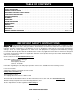
TABLE OF CONTENTS IMPORTANT SAFETY INSTRUCTIONS . . . . . . . . . . . . . . . . . . . . . . . . . . . . . . . . . . . . . . . . . . . . . . . . . . . . . . . . . . .2 SAFETY GUIDELINES . . . . . . . . . . . . . . . . . . . . . . . . . . . . . . . . . . . . . . . . . . . . . . . . . . . . . . . . . . . . . . . . . . . . . . . .3 GENERAL SAFETY RULES . . . . . . . . . . . . . . . . . . . . . . . . . . . . . . . . . . . . . . . . . . . . . . . . . . . . . . . . . . . . . . . . . . . .
SAFETY GUIDELINES - DEFINITIONS It is important for you to read and understand this manual. The information it contains relates to protecting YOUR SAFETY and PREVENTING PROBLEMS. The symbols below are used to help you recognize this information. Indicates an imminently hazardous situation which, if not avoided, will result in death or serious injury. Indicates a potentially hazardous situation which, if not avoided, could result in death or serious injury.
GENERAL SAFETY RULES READ AND UNDERSTAND ALL WARNINGS AND OPERATING INSTRUCTIONS BEFORE USING THIS EQUIPMENT. Failure to follow all instructions listed below, may result in electric shock, fire, and/or serious personal injury or property damage. IMPORTANT SAFETY INSTRUCTIONS 1. FOR YOUR OWN SAFETY, READ THE INSTRUCTION MANUAL BEFORE OPERATING THE MACHINE. Learning the machine’s application, limitations, and specific hazards will greatly minimize the possibility of accidents and injury. 2.
ADDITIONAL SAFETY RULES FOR BAND SAWS FAILURE TO FOLLOW THESE RULES MAY RESULT IN SERIOUS PERSONAL INJURY. 1. 2. 3. 4. 5. 6. 7. 8. 9. 10. 11. 12. 13. DO NOT OPERATE THIS MACHINE UNTIL it is assembled and installed according to the instructions. OBTAIN ADVICE from your supervisor, instructor, or another qualified person if you are not familiar with the operation of this tool. FOLLOW ALL WIRING CODES and recommended electrical connections. USE THE GUARDS WHENEVER POSSIBLE.
POWER CONNECTIONS A separate electrical circuit should be used for your machines. This circuit should not be less than #12 wire and should be protected with a 20 Amp time lag fuse. If an extension cord is used, use only 3-wire extension cords which have 3prong grounding type plugs and matching receptacle which will accept the machine’s plug.
3. Grounded, cord-connected machines intended for use on a supply circuit having a nominal rating between 150 - 250 volts, inclusive: GROUNDED OUTLET BOX CURRENT CARRYING PRONGS If the machine is intended for use on a circuit that has an outlet that looks like the one illustrated in Fig. C, the machine will have a grounding plug that looks like the plug illustrated in Fig. C. Make sure the machine is connected to an outlet having the same configuration as the plug.
FUNCTIONAL DESCRIPTION FOREWORD Delta Model 28-682 is an 18" Wood Cutting Band Saw. This machine has speeds of 2300 and 3250 SFPM (surface feet per minute). Its blade to frame capacity is 171/2" and its height under guide capacity is 12". The band saw has a quick blade tensioning mechanism for ease of changing blades. The Delta Model 28-682 has a large 173/4"x18" cast iron table that can be tilted 48 degrees to the right and 10 degrees to the left. The band saw also comes with a 4" O.D.
UNPACKING AND CLEANING Carefully unpack the machine and all loose items from the shipping container(s). Remove the protective coating from all unpainted surfaces. This coating may be removed with a soft cloth moistened with kerosene. (Do not use acetone, gasoline or lacquer thinner for this purpose.) After cleaning, cover the unpainted surfaces with a good quality household floor paste wax. 1. 2. B A Remove the four bolts (A) Fig. 1 (three of which are shown) that attach the saw (B) to the shipping skid.
TABLE 1. 2. Remove the table pin (A) Fig. 5. Align the blade with the table slot (B) Fig. 5. Slide the table until the blade has reached the center cutout (C) Fig. 5, then rotate the table 90 degrees toward the front of the machine. NOTE: Make sure that the table slot (B) Fig. 6 is facing toward the right of the machine. 3. Align the two table studs (A) Fig. 6, in the bottom of the table, with the two holes in the trunnion assemblies. 4. Thread the trunnion lock knob (D) Fig. 7 onto the table stud.
FENCE 1. Align the two holes (A) Fig. 9 in the front fence rail with the two holes (B) in the front of the table. NOTE: Make sure that the scale on the front fence rail is facing upward. 2. Insert a 1/4-20 x 1-1/2" socket-head cap screw through one of the holes (A) Fig. 9 hole in the front fence rail. Place a spacer on the screw between the front fence rail and the table. Thread the screw into the front of the table. Repeat for the other hole (A) in the front fence rail.
OPERATION OPERATIONAL CONTROLS AND ADJUSTMENTS STARTING AND STOPPING SAW The power switch is located on the left side of the machine. To turn the machine “ON”, push the green start button (A) Fig. 14. To turn the machine “OFF”, push the red stop button (B). LOCKING SWITCH IN THE “OFF” POSITION IMPORTANT: When the tool is not in use, the switch should be locked in the “OFF” position to prevent unauthorized use, using a padlock (C) Fig. 15 with a 3/16" diameter shackle. A C B Fig. 14 Fig.
4. Raise the blade tension lever to the “up” position and turn it clockwise to increase tension or counterclockwise to relieve the tension. 5. After the first turn, lower the blade tension lever and check the tension scale. If the tension is still not correct, repeat the procedure. The tension scale is correct for standard blades used on average work.
CHANGING SPEEDS DISCONNECT MACHINE FROM POWER SOURCE. 1. 2. 3. 4. 5. Open the bottom access door (See D, Fig. 26). Locate and loosen motor release handle (C) Fig. 20A inset by turning it counter-clockwise. Lift up motor assembly and move belt (A) to desired groove on motor pulley (B). Move belt to outer groove (D) for 2300 SFPM, or to inner groove (E) for 3250 SFPM. Push down on motor assembly and then turn motor release handle (C) clockwise to tighten belt. Close the bottom access door.
ADJUSTING THE TABLE POSITIVE STOP A DISCONNECT MACHINE FROM POWER SOURCE. This machine is equipped with a positive stop that allows the table to be rapidly positioned at 90 degrees to the blade after the table has been tilted. To check and adjust: 1. Place the table in the 90 degree position and lock it in place. 2. Place a square (A) Fig. 24 on the table with one end against the blade to check for 90 degrees. 3. If an adjustment is necessary, loosen the locknut (B) Fig.
A A Fig. 28 Fig. 28A ADJUSTING RESAW GAUGE The resaw gauge (A) attaches to the fence (Fig. 28). Slide it along the fence slot until the edge is slightly in front of the blade teeth. Use this gauge for resawing operations and for cutting warped workpieces. ADJUSTING BELT TENSION If it becomes necessary to adjust the belt tension on the machine, turn the motor release handle (A) Fig. 28A counterclockwise. Lower or raise the motor, and when adjustment is complete, tighten the motor release handle (A).
BAND SAW BLADES A band saw blade is a delicate piece of steel that is subjected to tremendous strain. You can obtain long use from a band saw blade if you use it properly. Be sure you use blades of the proper thickness, width and temper for the various types of material and cuts. Always use the widest blade possible. Use narrow blades only for sawing small, abrupt curves and for fine, delicate work. This will save blades and 1 will produce better cuts.
Trouble: BAND SAW VIBRATES EXCESSIVELY. Probable Cause 1. Machine not mounted securely to stand. 2. Stand on uneven surface. 3. Worn belt. 4. Pulley not aligned. 5. Motor not fastened securely. Remedy 1. Tighten all mounting hardware. 2. Reposition on flat level surface. 3. Replace belt. 4. Adjust pulleys. 5. Tighten all mounting hardware. Trouble: BAND SAW DOES NOT COME UP TO SPEED. Probable Cause 1. Low voltage due to improper extension cord size. 2. Low voltage. Remedy 1.
MAINTENANCE KEEP MACHINE CLEAN LUBRICATION Periodically blow out all air passages with dry compressed air. All plastic parts should be cleaned with a soft damp cloth. NEVER use solvents to clean plastic parts. They could possibly dissolve or otherwise damage the material. Apply household floor paste wax to the machine table and extension table or other work surface weekly.
PORTER-CABLE • DELTA SERVICE CENTERS (CENTROS DE SERVICIO DE PORTER-CABLE • DELTA) Parts and Repair Service for Porter-Cable • Delta Machinery are Available at These Locations (Obtenga Refaccion de Partes o Servicio para su Herramienta en los Siguientes Centros de Porter-Cable • Delta) ARIZONA Tempe 85282 (Phoenix) 2400 West Southern Avenue Suite 105 Phone: (602) 437-1200 Fax: (602) 437-2200 CALIFORNIA Ontario 91761 (Los Angeles) 3949A East Guasti Road Phone: (909) 390-5555 Fax: (909) 390-5554 Tampa 3360