(Model 36-085) PART NO. 901694 - 08-31-01 Copyright © 2001 Delta Machinery To learn more about DELTA MACHINERY visit our website at: www.deltamachinery.com. For Parts, Service, Warranty or other Assistance, please call ESPAÑOL: PÁGINA 19 1-800-223-7278 (In Canada call 1-800-463-3582).
GENERAL SAFETY RULES Woodworking can be dangerous if safe and proper operating procedures are not followed. As with all machinery, certain hazards are involved with the operation of the product. Using the machine with respect and caution will considerably lessen the possibility of personal injury. However, if normal safety precautions are overlooked or ignored, personal injury to the operator may result.
ADDITIONAL SAFETY RULES FOR MITER SAWS 20. NEVER lock the switch in the “ON” position. 1. USE ONLY CROSS-CUTTING SAW BLADES. When using carbide tipped blades, be certain that they have a negative hook angle. Do not use blades with deep gullets. These can deflect and contact the guard. 21. AFTER COMPLETING CUT, release power switch and wait for coasting blade to stop before returning saw to raised position. 2.
CONNECTING TOOL TO POWER SOURCE POWER CONNECTIONS A separate electrical circuit should be used for your tools. This circuit should not be less than #12 wire and should be protected with a 20 Amp time lag fuse. If an extension cord is used, use only 3-wire extension cords which have 3prong grounding type plugs and matching receptacle which will accept the tool’s plug.
EXTENSION CORDS MINIMUM GAUGE EXTENSION CORD RECOMMENDED SIZES FOR USE WITH STATIONARY ELECTRIC TOOLS Ampere Rating Use proper extension cords. Make sure your extension cord is in good condition and is a 3-wire extension cord which has a 3-prong grounding type plug and matching receptacle which will accept the tool’s plug. When using an extension cord, be sure to use one heavy enough to carry the current of the tool.
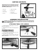
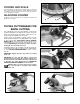
CARTON CONTENTS IMPORTANT: DO NOT LIFT THE MITER SAW BY THE SWITCH HANDLE. THIS ACTION CAN CAUSE MISALIGNMENT. ALWAYS LIFT THE MACHINE BY THE BASE OR CARRYING HANDLE. 1 - Miter Saw 5 - Table Lock Handle 2 - Dust Bag 6 - Extension (2) 3 - Work Clamp 7 - Stock Stop 4 - Wrench 8 - Retaining Bracket (2) 1 7 2 8 5 3 4 6 Fig.
ATTACHING STOCK STOP AND TABLE EXTENSIONS A 1. Decide on which side of the saw table you want the stock stop (A) Fig. 8, and attach the stock stop (A) on the table extension (B). B Fig. 8 2. Insert the ends of table extension (B) Fig. 9 into the two holes on the end of the saw base and into the two holes of retaining bracket (C). Tighten the screw (D) to hold the table extension in place. C D 3. Attach the left hand table extension (E) Fig. 10 in the same manner. Fig.
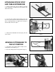
A ATTACHING DUST BAG C B 1. Attach the dust bag (A) Fig. 13, to the dust spout (B). Be certain that the wire ring (C) is engaged in the spout groove. Fig. 13 FASTENING MACHINE TO SUPPORTING SURFACE A Before operating this tool, firmly mount it to a sturdy workbench or other supporting surface. Four holes are provided, two of which are shown at (A) Fig. 14, for this purpose. If the tool is to be moved frequently, mount it to a 3/4″ piece of plywood.
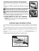
STARTING AND STOPPING THE MACHINE To start the machine, squeeze the trigger (A) Fig. 16. To stop the machine, release the trigger. This miter saw is equipped with an automatic electric blade brake. As soon as the trigger (A) Fig. 16, is released, the electric brake will be activated and will stop the blade in seconds. A WARNING: A TURNING SAW BLADE CAN BE HAZARDOUS. AFTER COMPLETING THE CUT, RELEASE THE TRIGGER (A) FIG. 16 TO ACTIVATE THE BLADE BRAKE.
B A A POINTER AND SCALE A pointer (B) Fig. 19 indicates the actual angle of cut. Each line on the scale (C) represents 1 degree. When the pointer is rotated from one line to the next on the scale, the angle of cut is changed by 1 degree. ADJUSTING POINTER To adjust, loosen screw (D) Fig. 19, adjust the pointer, and tighten the screw (D). C D Fig. 19 TILTING CUTTINGHEAD FOR BEVEL CUTTING The cuttinghead of the saw can be tilted to cut any bevel angle from 0 degrees to 45 degrees, left or right.
A A Fig. 22 Fig. 23 REAR SUPPORT/CARRYING HANDLE A rear stabilizer bar (A) Fig. 22, is provided to prevent the miter saw from tipping to the rear when the cuttinghead is returned to the up position after a cut has been made. For maximum support the bar (A) should be pulled out as far as possible. WARNING: BE CERTAIN THAT THE STABILIZER BAR IS FULLY EXTENDED WHEN MAKING CUTS. The support bar (A) (Fig. 23) also acts as a carrying handle when transporting the saw.
ADJUSTING THE FENCE 90 DEGREES TO THE BLADE B C The fence (A) Fig. 27 should be adjusted so that it is 90 degrees to the blade. To adjust: 1. DISCONNECT TOOL FROM POWER SOURCE. 2. First, adjust the blade so that it is parallel to the table slot. A C 3. Use a square (B) Fig. 27 with one end against the fence (A) and the other end against the slot in the table. 4. Loosen the four screws (C) Fig. 27, adjust the fence 90 degrees to the table opening, and tighten the four screws (C). Fig.
2. Set the saw blade on the “0” degree positive miter stop. 3. Use one end of a square (A) Fig. 29 on the table and the other end against the blade. Check to see if the blade is 0 degrees to the table (Fig. 29). 4. If an adjustment is necessary, loosen the locknut (B) Fig. 30, and turn the screw (C) until head of the screw (C) contacts the 0 degree bevel stop (D) when the blade is 90 degrees to the table. Tighten locknut (B). NOTE: The bevel cover has been removed in Fig. 30 for clarity. 5.
TYPICAL OPERATIONS AND HELPFUL HINTS 1. Before cutting, be certain that the cutting arm and table are at their correct settings and are firmly locked in place. Also, determine that the workpiece is the right size for the saw. 2. Firmly clamp the workpiece to the table against the fence. Fig. 35 illustrates the work clamp (A) used to clamp the workpiece to the fence. The clamp (A) can also be used on the right side of the machine. A 3. For best results, cut at a slow, even cutting rate. 4.
CUTTING BOWED MATERIAL If the workpiece is bowed, position it on the table with the bowed part up and against the fence (Fig. 39). If the material is positioned the wrong way (Fig. 40), the workpiece will pinch the blade near the completion of the cut. RIGHT WRONG Fig. 39 Fig. 40 CUTTING CROWN MOLDING One of the many features of a compound miter saw is the ease of cutting crown molding. The following is an example of cutting both inside and outside corners on 52/38 degree wall angle crown molding.
D C A B Fig. 43 Fig. 44 MAINTENANCE CHANGING THE BLADE WARNING: USE ONLY CROSS-CUTTING BLADES. WHEN USING CARBIDE TIPPED BLADES, BE CERTAIN THAT THEY HAVE A NEGATIVE HOOK ANGLE. USE ONLY 10″″ DIAMETER SAW BLADES RATED FOR 6000 RPM OR HIGHER AND HAVE 5/8″″ DIAMETER ARBOR HOLES. 1. DISCONNECT TOOL FROM POWER SOURCE. 2. Remove the screw (A) Fig. 45, and rotate the cover (B) to the rear (Fig. 46). 3. Depress the arbor lock (A) Fig. 47, to keep the blade from turning. 4. Use the supplied wrench (D) Fig.
A G F E D Fig. 48 Fig. 47 BRUSH INSPECTION AND REPLACEMENT CAUTION: BEFORE INSPECTING THE BRUSHES, DISCONNECT THE TOOL FROM THE POWER SOURCE. Brush life varies, depending on the load on the motor. Check the brushes after the first 50 hours of use for a new machine, or after a new set of brushes has been installed. After the first check, examine them after about every 10 hours of use until replacement is necessary. To inspect the brushes: B 1. Remove three screws (A) Fig.
ACCESSORIES A complete line of accessories is available from your Delta Supplier, Porter-Cable • Delta Factory Service Centers, and Delta Authorized Service Stations. Please visit our Web Site www.deltamachinery.com for a catalog or for the name of your nearest supplier. WARNING: Since accessories other than those offered by Delta have not been tested with this product, use of such accessories could be hazardous. For safest operation, use only Delta recommended accessories with this product.
PORTER-CABLE • DELTA SERVICE CENTERS (CENTROS DE SERVICIO DE PORTER-CABLE • DELTA) Parts and Repair Service for Porter-Cable • Delta Power Tools are Available at These Locations (Obtenga Refaccion de Partes o Servicio para su Herramienta en los Siguientes Centros de Porter-Cable • Delta) ARIZONA Tempe 85282 (Phoenix) 2400 West Southern Avenue Suite 105 Phone: (602) 437-1200 Fax: (602) 437-2200 CALIFORNIA Ontario 91761 (Los Angeles) 3949A East Guasti Road Phone: (909) 390-5555 Fax: (909) 390-5554 San Lean