
Instruction manual


Porter Cable 7529 & 8529
Porter Cable 7529 & 8529
© 2000-2005 Router Technologies
All Rights Reserved
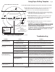
Note: Cross lines for locating and drilling holes are accurate. The illustration of subbase may vary
slightly in size and design, but is accurate enough for cutting the rubber spacer if required.
Page 41
Refer to pages 28, 31, 32 before using template
Additional Templates Available on Website
Router Raizer Access Hole
3/4" reference circle for drilling the
routers original subbase only. Table
mounted, drill 1/2" hole in table top.
.500" reference circle
for drilling table top or
insert plate.
1/2" = .500
Router table fence reference line
Router mounting holes
Use this 6" scale to check accuracy when copied
Drill .500" hole
through router
table insert plate
install #30 dust cover insert
into .500" hole and press flush
with top of insert plate
Router Raizer Access Hole
NOTE: This router requires a 3/4" pocket or use of 8" X 8"
black rubber spacer for router table installation. Pages 4,5,6.
NOTE: This hole must be drilled 1/2" or .500"
for #30 dust cover insert to fit properly.
Cut Out of
Rubber spacer
if Required
Cut Out of
Rubber spacer
if Required