
Technical data


ENGLISH
en - 3 17
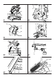
1 Allen key 4 mm
1 Allen key 6 mm
1 Two-pin spanner
1 Dust extraction adapter for top guard
1 Instruction manual
1 Exploded drawing
• Check for damage to the tool, parts or accessories which may have
occurred during transport.
• Take the time to thoroughly read and understand this manual prior to
operation.
• Remove the saw from the packaging material carefully.
• Release the head lock down knob to raise the head of the machine.
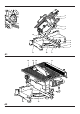
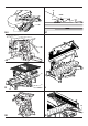
Description (fig. A1 - A4)
Your DEWALT table top mitre saw has been developed for professional
applications. This high precision machine can be easily and quickly set to
crosscut, bevel, mitre, or compound mitre.
A1
1 On/off-switch
2 Head lock up release lever
3 Additional saw bench table locking knob
4 Moveable lower blade guard
5 Fixed table
6 Blade slot
7 Positive stop lever
8 Mitre clamping knob
9 Rotating table/mitre arm
10 Mitre scale
11 Fence
12 Bevel clamp handle
13 Head lock down knob
A2
14 Saw bench table
15 Riving knife
16 Upper saw blade guard
17 Rip fence
18 Fixed lower guard (for use in bench saw position)
19 Attachment mounting holes
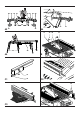
Optional accessories
A3
20 Table end plate (DE3490)
21 Support guide rails 1000 mm (DE3494)
22 Material support plate (DE3495)
23 Material clamp (DE3499)
24 Swivelling stop (DE3462)
25 Adjustable stand 760 mm (max. height) (DE3477)
26 Legstand (DE3493)
A4
27 Length stop for short workpieces (to be used with guide rails [21])
(DE3492)
A5
28 Legstand (DE3493)
29 Roller table (DE3497)
Electrical safety
The electric motor has been designed for one voltage only. Always check
that the power supply corresponds to the voltage on the rating plate.
Mains plug replacement (U.K. & Ireland only)
• Should your mains plug need replacing and you are competent to do
this, proceed as instructed below. If you are in doubt, contact an
authorized DEWALT repair agent or a qualified electrician.
• Disconnect the plug from the supply.
• Cut off the plug and dispose of it safely; a plug with bared copper
conductors is dangerous if engaged in a live socket outlet.
• Only fit 13 Amperes BS1363A approved plugs fitted with the correctly
rated fuse (1).
• The cable wire colours, or a letter, will be marked at the connection
points of most good quality plugs. Attach the wires to their respective
points in the plug (see below). Brown is for Live (L) (2), blue is for
Neutral (N) (4) and green/yellow is for Earth (E).
• Before replacing the top cover of the mains plug ensure that the cable
restraint (3) is holding the outer sheath of the cable firmly and that the
leads are correctly fixed at the terminal screws.
Never use a light socket.
Never connect the live (L) or neutral (N) wires to the earth pin
marked E or .
For 115 V units with a power rating exceeding 1500 W, we recommend to
fit a plug to BS4343 standard.
Using an extension cable
If an extension cable is required, use an approved extension cable suitable
for the power input of this machine (see technical data). The minimum
conductor size is 1.5 mm
2
. When using a cable reel, always unwind the
cable completely. Also refer to the table below.
Conductor size (mm
2
) Cable rating (Amperes)
0.75 6
1.00 10
1.50 15
2.50 20
4.00 25
Cable length (m)
7.5 15 25 30 45 60
Voltage Amperes Cable rating (Amperes)
230 0 - 2.0 6 6 6 6 6 6
2.1 - 3.4 6 6 6 6 6 6
3.5 - 5.0 6 6 6 6 10 15
5.1 - 7.0 10 10 10 10 15 15
7.1 - 12.0 15 15 15 15 20 20
12.1 - 20.0 20 20 20 20 25 -
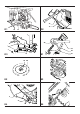
Assembly and adjustment
Prior to assembly and adjustment always unplug the tool.
Mounting the upper guard (fig. B)
• Fasten the guard (30) to the riving knife (31) with the bolt (32).
Place the washer and wingnut onto the other end of the bolt and tighten.
• Fit the dust spout (33) to the blade guard.
A separate dust kit is available as an option (DE7779).