
Technical data


20 en - 6
ENGLISH
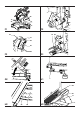
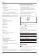
Bevel cross-cut (fig. A1, G1 & M)
Bevel angles can be set from 0° to 48° to the left. Bevels up to 45° can be
cut with the head set between zero and a maximum of 45° mitre position
right or left (fig. M).
• Loosen the bevel clamp handle (12) and set the bevel as desired (fig. A1).
• Use the 45°/48° adjustment handle (50) if required (fig. G1).
• Tighten the bevel clamp handle firmly.
• Proceed as for a vertical straight cross-cut.
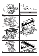
Sawing in the bench mode
Ripping (fig. A1, A2, C1, D1 & N)
• Set the blade to the vertical position.
• Loosen the table locking knobs, both main (37) (fig. D1) and additional
(3) (fig. A1), but do not take off. Set the depth of cut by sliding the table
(14) (fig. A2) up or down. The correct position is to have the tips of
three teeth above the top surface of the wood.
• Loosen the sliding fence locking knob (35) (fig. C1) and slide the sliding
fence front or rear in order to support as much of the workpiece as
possible. At least the rear end of the fence should be level with the
front of the riving knife.
• Lock the table locking knobs tightly.
• Ensure the plastic guard plate (18) is in fixed position (fig. A2).
• Ensure that the rip fence is parallel with the blade.
• Set the rip fence for the width of cut required by using the scale let into
the front of the table. Set the sliding rip fence to the required position.
• Switch on the machine.
• Slowly feed the workpiece underneath the front of the upper blade
guard, keeping it firmly pressed against the rip fence. Allow the teeth to
cut and do not force the workpiece through the blade. The blade
speed should be kept constant.
• Remember to always use the push stick (57) (fig. N).
• After completing the cut, switch off the machine.
Optional accessories
Dust extraction
A dust extraction kit (DE7779) is available for optimal dust extraction.
Clamping the workpiece (fig. A3)
• In most cases, the action of the blade is sufficient to hold the material
firmly against the fence.
• If the material has a tendency to lift or come forward from the fence,
preferably use the optional material clamp (23).
• Always use the clamp if cutting non-ferrous metals.
Sawing short workpieces (fig. A3)
It is advisable to use the length stop for short workpieces (27) both for batch
sawing and for short individual workpieces of different lengths. The length
stop can only be used in conjunction with a pair of optional guide rails (21).
Sawing long workpieces (fig. A3)
Always support long workpieces.
Figure A3 shows the ideal configuration for sawing long workpieces when
the saw is used free-standing (all items available as an option).
These items (except the legstand and the material clamp) are required
both on the infeed and the outfeed side:
- Legstand (28) (supplied with mounting instructions).
- Guide rails (500 or 1,000 mm) (21).
- Stands (25) to support the guide rails. Do not use the stands to
support the machine! The height of the stands is adjustable.
- Material support plates (22).
- Table end plate (20) for supporting the rails (also when working on
an existing bench).
- Material clamp (23).
- Swivelling stop (24).
• Place your saw on the legstand and fit the guide rails.
• Firmly screw the material support plates (22) to the guide rails (21).
• Install the table end plates (20).
• Install the swivelling stop (24) to the rear rail.
• Use the swivelling stop (24) to adjust the length of medium and long
workpieces. It can be adjusted sideways or swung out of the way
when not in use.
Using the roller table (fig. A3 & A5)
The roller table (33) makes the handling of large and long pieces of wood
very easy (fig. A5). It can be connected either to the left or to the right of the
machine. The roller table requires the use of the optional legstand (fig. A3).
Assemble the roller table following the instructions supplied
with the legstand.
• Replace the short support bars provided with the legstand with the
irregular rails from the table on the side the table is to be used.
• Follow all instructions provided with the roller table.
Range of saw blades available (recommended blades)
Type of blade Blade dimensions Usage
DT1529 series 40 260x30x24 For cutting wood along the grain,
block board, plywood and MDF.
Coarse cut.
DT1531 series 40 260x30x48 For cutting wood along the grain,
block board, plywood and MDF.
Medium cut.
DT1530 series 40 260x30x80 For cutting wood, wood products,
plastics and aluminium. Fine cut.
DT1735 series 60 260x30x24 For cutting wood along the grain,
block board, plywood and MDF.
Coarse cut.
DT1736 series 60 260x30x48 For combination cutting in wood, block
board, plywood and MDF. Medium cut.
DT1737 series 60 260x30x80 For cutting wood, wood products
and plastics. Not for aluminium!
Fine cut.
Consult your dealer for further information on the appropriate accessories.
Transporting
To facilitate carrying, pull down the head and push in the head lock down
knob (13).
Maintenance
Your DEWALT Power Tool has been designed to operate over a long
period of time with a minimum of maintenance. Continuous satisfactory
operation depends upon proper tool care and regular cleaning.
Unwanted tools and the environment
Take your tool to an authorized DEWALT repair agent where it will be
disposed of in an environmentally safe way.