www. .
Figure 1A c d b e a f g i h j w k l v m t n u o p s q r Figure 1B x hh y aa gg z bb ff ee cc dd 1
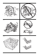
Figure 2 Figure 3 jj ii Figure 5 Figure 4 kk ll Figure 6 Figure 7 nn mm 2
Figure 8 Figure 9 oo Figure 10A Figure 10B b a pp a cc Figure 10C Figure 10D ss tt qq rr pp cc 3
Figure 11 Figure 12 vv xx yy k zz v a1 a2 ww uu s a3 u a4 a5 Figure 14 Figure 13 a6 u Figure 16 Figure 15 u 4 a7 a8
Figure 17A Figure 17B Figure 18 Figure 19 Figure 20 Figure 21 A B 5
Figure 22 Figure 23 “A” Figure 24B Figure 24A n ll q q n Figure 25B Figure 25A ss ss n 6 n
Figure 26A Figure 26B Figure 27 a Figure 28B Figure 28A m a9 o o 7
EN GL I S H MITRE SAW DWS780 Congratulations! An estimation of the level of exposure to vibration should also take into account the times when the tool is switched off or when it is running but not actually doing the job. This may significantly reduce the exposure level over the total working period. You have chosen a DEWALT tool. Years of experience, thorough product development and innovation make DEWALT one of the most reliable partners for professional power tool users.
ENGLI SH Safety Instructions WARNING! When using electric tools basic safety precautions should always be followed to reduce the risk of fire, electric shock and personal injury including the following. Read all these instructions before attempting to operate this product and save these instructions. SAVE THIS MANUAL FOR FUTURE REFERENCE General Safety Rules 1. Keep work area clear. Cluttered areas and benches invite injuries. 2. Consider work area environment. Do not expose the tool to rain.
EN GL I S H • Do not use HIGH SPEED STEEL blades. • Do not use cracked or damaged saw blades. Turn the machine on and start new cutting operation with reduced feed force. • Do not use any abrasive or diamond discs. • Never cut light alloy, especially magnesium. • Never use your saw without the kerf plate. • Whenever the situation allows, mount the machine to a bench using bolts with a diameter of 8 mm and 80 mm in length. • Before each cut ensure that the machine is stable.
ENGLI SH 1 Material clamp Fig. 6 1 Instruction manual mm. DE7053-XJ Dustbag 1 Exploded drawing • Check for damage to the tool, parts or accessories which may have occurred during transport. • Take the time to thoroughly read and understand this manual prior to operation. Description (fig. 1A–8) WARNING: Never modify the power tool or any part of it. Damage or personal injury could result. Fig. 1A a. Lower guard b. Head up-lock release lever c. Operating handle d. Carrying handle e. Motor housing f.
EN GL I S H ASSEMBLY AND ADJUSTMENTS WARNING: To reduce the risk of injury, turn unit off and disconnect machine from power source before installing and removing accessories, before adjusting or changing set-ups or when making repairs. Be sure the trigger switch is in the OFF position. An accidental startup can cause injury. Unpacking (fig. 1A, 9) 1. Open the box and lift the saw out by the convenient carrying handle (d), as shown in figure 9. 2. Place the saw on a smooth, flat surface. 3.
ENGLI SH 22.5° BEVEL PAWLS (FIG. 12) BEVEL POINTER ADJUSTMENT (FIG. 12) Your saw is equipped to rapidly and accurately set a 22.5° bevel, left or right. The 22.5° bevel pawl (a2) can be rotated to contact the crown adjustment screw (zz). If the bevel pointers (yy) do not indicate zero, loosen each screw (xx) that holds each bevel pointer in place and move them as necessary. Ensure the 0° bevel is correct and the bevel pointers are set before adjusting any other bevel angle screws. RAIL LOCK KNOB (FIG.
EN GL I S H MITRE LOCK ADJUSTMENT (FIG. 1A, 16) The mitre lock rod (a7) should be adjusted if the table of the saw can be moved when the mitre lock handle is locked (down). 1. Put the mitre lock handle (u) in the unlocked (up) position. 2. Using a 13 mm (1/2") open end wrench, loosen the lock nut (a8) on the mitre lock rod. 3. Using a slotted screwdriver, tighten the mitre lock rod by turning it clockwise as shown in figure 16. Turn the lock rod until it is snug, then turn counterclockwise one turn. 4.
ENGLI SH MITRE CROSSCUT The mitre angle angle is often 45° for making corners, but can be set anywhere from zero to 50° left or 60° right. Proceed as for a straight vertical crosscut. When performing a mitre cut on workpieces wider than 51 x 105 mm (2" x 4") that are shorter in length, always place the longer side against the fence (fig. 19). BEVEL CUT Bevel angles can be set from 49° right to 49° left and can be cut with the mitre arm set between 50° left or 60° right.
EN GL I S H The chart (Table 1) shown below will assist you in selecting the proper bevel and mitre settings for common compound mitre cuts. INSTRUCTIONS FOR CUTTING CROWN MOULDING LAYING FLAT AND USING THE COMPOUND FEATURES (FIG. 24A) • Select the desired angle A (fig. 22) of your project and locate that angle on the appropriate arc in the chart. 1. Moulding should lay flat with the broad back surface down on the saw table.
ENGLI SH CUTTING LARGE MATERIAL (FIG. 27) Occasionally you will encounter a piece of wood a little too large to fit beneath the lower guard. If this occurs, place your right thumb on the upper side of the guard (a) and roll the guard up just enough to clear the workpiece, as shown in figure 27. Avoid doing this as much as possible, but if need be, the saw will operate properly and make the bigger cut. NEVER TIE, TAPE, OR OTHERWISE HOLD THE GUARD OPEN WHEN OPERATING THIS SAW.
EN GL I S H CROWN MOULDING FENCE: DE7084-XJ GUARANTEE The crown moulding fence (ll) is used for precision cutting of crown moulding. DEWALT is confident of the quality of its products and offers an outstanding guarantee for professional users of the product. This guarantee statement is in addition to and in no way prejudices your contractual rights as a professional user or your statutory rights as a private non-professional user.