
Supplementary Document


www.powers.com
2
ADHESIVES
REFERENCE DATA (ASD)
TECH MANUAL – ADHESIVES ©2016 POWERS VOLUME 1 – REV. M
REFERENCE DATA (ASD)
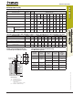
Allowable Stress Design (ASD) Installation Table for AC100+ Gold (Solid Concrete Base Materials)
Dimension/Property Notation Units Nominal Anchor Size
Threaded rod - - 3/8" 1/2" - 5/8" 3/4’" 7/8" 1" - 1-1/4" -
Reinforcing bar - - #3 - #4 #5 #6 #7 #8 #9 - #10
Nominal anchor diameter d
in.
(mm)
0.375
(9.5)
0.500
(12.7)
0.625
(15.9)
0.750
(19.1)
0.875
(22.2)
1.000
(25.4)
1.125
(28.6)
1.250
(31.8)
1.250
(31.8)
Nominal diameter of drilled hole d
bit
in.
7/16
ANSI
9/16
ANSI
5/8
ANSI
11/16
or 3/4
ANSI
7/8
ANSI
1
ANSI
1-1/8
ANSI
1-3/8
ANSI
1-3/8
ANSI
1-1/2
ANSI
Minimum nominal embedment depth h
nom
in.
(mm)
2-3/8
(61)
2-3/4
(70)
3-1/8
(79)
3-1/2
(89)
3-1/2
(89)
4
(102)
4-1/2
(114)
5
(127)
5
(127)
Maximum torque
(only possible
after full cure
time of adhesive)
A36 or F1554
carbon steel rod
T
max
ft.-lb.
(N-m)
10
(13)
25
(34)
50
(68)
90
(122)
125
(169)
165
(224)
-
280
(379)
-
F593 Condition CW stainless
steel rod or ASTM A193,
Grade B7 carbon steel rod
T
max
ft.-lb.
(N-m)
16
(22)
33
(45)
60
(81)
105
(142)
125
(169)
165
(224)
-
280
(379)
-
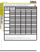
Allowable Stress Design (ASD) Installation Table for AC100+ Gold (Hollow Base Material with Screen Tube)
Dimension/Property Notation Units Nominal Size - Stainless Steel Nominal Size - Plastic
Threaded Rod - - 1/4" 3/8" 1/2" 5/8" 3/4" 1/4" 3/8" 1/2" 5/8"
Nominal threaded rod diameter d
in.
(mm)
0.250
(6.4)
0.375
(9.5)
0.500
(12.7)
0.625
(15.9)
0.750
(19.1)
0.250
(6.4)
0.375
(9.5)
0.500
(12.7)
0.625
(15.9)
Nominal screen tube diameter - in. 1/4 3/8 1/2 5/8 3/4 1/4 3/8 1/2 5/8
Nominal diameter of drilled hole d
bit
in.
(mm)
3/8
ANSI
1/2
ANSI
5/8
ANSI
3/4
ANSI
7/8
ANSI
1/2
ANSI
9/16
ANSI
3/4
ANSI
7/8
ANSI
Maximum torque
(only possible after full cure time of adhesive)
T
max
ft.-lbf.
(N-m)
4
(5)
6
(8)
10
(14)
10
(14)
10
(14)
4
(5)
6
(8)
10
(14)
10
(14)
Detail of Steel Hardware Elements
used with Injection Adhesive System
Threaded Rod and Deformed Reinforcing
Bar Material Properties
T
max
h
nom
h
c
c
s
d
d
o
(d
bit
)
Threaded Rod
or Rebar
Nomenclature
d = Diameter of anchor
d
bit
= Diameter of drilled hole
h = Base material thickness
The greater of:
[h
nom
+ 1-1/4"] and [h
nom
+ 2d
bit
]
h
nom
= Minimum embedment depth
Steel
Description
(General)
Steel
Specification
(ASTM)
Nominal
Anchor Size
(inch)
Minimum
Yield Strength,
f
y
(ksi)
Minimum
Ultimate
Strength,
f
u
(ksi)
Carbon Rod
A 36 or F1554
Grade 36
3/8 through 1-1/4 36.0 58.0
Stainless Rod
(Alloy 304 / 316)
F 593,
Condition CW
3/8 through 5/8 65.0 100.0
3/4 through 1-1/4 45.0 85.0
High Strength
Carbon Rod
A 193
Grade B7
3/8 through 1-1/4 105.0 125.0
Grade 60
Reinforcing Bar
A 615, A 767,
or A 996
3/8 through 1-1/4
(#3 through #10)
60.0 90.0
Grade 40
Reinforcing Bar
A 615 or A 767
3/8 through 1-1/4
(#3 through #6)
40.0 60.0