
Use and Care Manual


ENGLISH
4
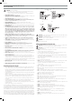
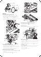
Installing the Cutting Wheel (Fig. A, C, K, P)
1. Loosen (do not remove) the cutting wheel cover knob
20
on the side of the cutting wheel
cover
5
. Pull the rubber side flap back and lift the cover toward the rear of thesaw.
2. Press spindle lock button
33
. Remove the cutting wheel nut
30
with cutting wheel
wrench
25
provided. Remove outer flange
31
.
3. Install the cutting wheel
6
against the inner flange
32
with the rotational arrow facing
the same way as on the rotational arrow on the cutting wheel cover. Press the spindle lock
button
33
while tightening the cutting wheelnut.
4. Replace cover and tighten the cutting wheel cover knob
20
.
5. Adjust cutting wheel depth (Refer to Depth ofCut).
Fig. J
29
Fig. I
27
55
28
26
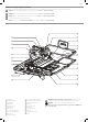
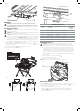
Assembling the Water Pump and Water Attachments
(Fig. A, I, J)
1. Place the threaded fitting
26
onto the water pump
27
. Attach the clear water tube
28
to the threaded fitting (Fig.I).
NOTE: The ideal position for the water pump is in the front left corner of water pan, near
the drainplug.
2. Insert the pump power cord into the socket
29
(Fig. J) or plug it into a separate GFCI
protectedreceptacle.
3. Fill the pan with 5 gallons clean of water. The pump should besubmerged.
NOTE: For longer pump life, always place the pump in a clean watersource.
NOTE: The edge of the water pan
55
is the maximum fill line. DO NOT fill the water pan
above the maximum water fillline.
4. Install the small rear water attachment
8
, large rear water attachment
9
, and splash
guard
10
ifneeded.
5. Install the small cutting cart water attachment
12
and large cutting cart water
attachment
13
ifneeded.
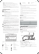
Attaching the Edge Guide (Fig. A, H)
1. Place edge guide
19
on the cutting cart assembly
11
.
2. Turn the edge guide lock
35
clockwise totighten.
Fig. G
18
Fig. F
16
11
Attaching the Cutting Cart (Fig. F, G, Y)
1. Turn the cutting cart stop knob
18
into the unlock position (Refer to Cutting Cart Stop
Knob) and slide the cutting cart onto therails.
2. Align the arrow on the rear of the cutting cart
11
with the arrow on the rail on the left of
the saw frame assembly
16
.
3. Slide the cutting cart assembly onto the rail system clearing the cutting cart stop knob
18
with therollers.
4. Rotate the cutting cart stop knob into either the first or second posistion to keep the
cutting cart on the rails during use. Refer to Cutting Cart Stop Knob for description
ofpositions.
Fig. E
2
19
16
Fig. H
11
19
35
Fig. D
53