
Use and Care Manual


ENGLISH
6
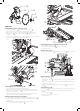
Water Nozzles (Fig V–X)
Water nozzles
17
are adjustable to provide maximum water for cutting and maximum
capacity with the minimum amount of overspray and mist. The adjusting lever
34
allows easy
adjustment of nozzles to desiredposition.
• Optimum position for minimum overspray (Fig.V).
• Water nozzles
17
can be fully retracted to allow for maximum capacity (Fig.W).
• “Off Cutting Wheel” position to eliminate water overspray between cuts and for the
cutting wheel change (Fig.X).
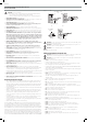
Fig. U
1
On/Off Switch (Fig. S, U)
WARNING: To avoid the possibility of the appliance plug or receptacle getting wet,
position the wet tile saw to one side of a wall mounted receptacle to prevent water
from dripping onto the receptacle or plug. The user should arrange a “drip loop” in the
cord connecting the saw to a receptacle (Fig. S). The “drip loop” is that part of the cord
below the level of the receptacle, or the connector if an extension cord is used, to prevent
water traveling along the cord and coming in contact with thereceptacle. Always plug
the saw into a GFCI receptacle and test to confirm the GFCI is operatingproperly. If the
plug or receptacle does get wet, DON'T unplug the cord. Disconnect the fuse or circuit
breaker that supplies power to the tool. Then unplug and examine for presence of water
in thereceptacle.
• To turn the wet tile saw on, lift up the on/off switch
1
.
• The wet tile saw locks onautomatically.
• To turn the tool off, push the on/off switchdown.
NOTE: A pad lock can be used on the switch to deter unauthorizeduse.
MAXIMUM TILE SIZES
Material
type
Size (up to)
inches (cm)
Max. weight Cut Cutting Cart
Stop Knob
Position
Tile 24x24x3/8 (60x60x1.0) 20 lbs. (9 kg) Rip cut or Crosscut 2
Tile 36x36x3/8 (90x90x1.0) 45 lbs. (20 kg) Rip or cross cut 1
Tile 37x8x3/8 (94x20x1.0) 10 lbs. (4.5 kg) Rip cut 1
Tile 37x8x3/8 (94x20x1.0) 10 lbs. (4.5 kg) Crosscut 2
Paver 12x12x2 (30.5x30.5x5.0) 26 lbs. (11.7 kg) Rip cut or Crosscut 2
Brick 8.5x4x2.5 (21.5x10.2x6.5) 7 lbs. (3.1 kg) Rip cut or Crosscut 2
Fig. S
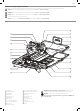
Fig. R
53
Tool Placement (Fig. R–T)
WARNING: When using the stand make sure to follow all the instructions and warnings
listed in the standmanual.
WARNING: When using large material ALWAYS make sure the pan stand bracket is being
used to keep the saw from tipping forward off thestand.
CAUTION: Tip Hazard. Excessive weight on the cart when the cart position knob is rotated
to position 1 could cause a tip hazard. Maximum tile size that can be cut is 36"x36"x3/8"
(90cm x 90cm x 1.0cm) (refer to Maximum Tile Size). Do not cut tile or other materials
that are thicker than 3/8" (1cm) thick while the cutting cart stop knob is in position 1.
When cutting narrow materials, rotate the cutting cart stop knob to position 2. This will
allow the cart to stay on the rail when pulled toward the user in front of the cuttingwheel.
1. Place stand (D24001, see Accessories) on a levelsurface.
2. Place the saw into the stand as shown in FigureR. The pan has two brackets
53
that wrap
around the front crossbar.
3. Rotate the pan stand bracket
24
in place around the rear crossbar.
If not using a stand, place saw on a levelsurface.
OPERATION
WARNING: To reduce the risk of serious personal injury, turn unit off and
disconnect it from power source before making any adjustments or removing/
installing attachments or accessories. An accidental start-up can causeinjury.
Fig. Q
36
5039
37
Fig. T
24