
Instruction manual


9
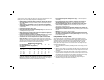
DC490, DW940, DW941 (FIG. 1, 5, 6)
To remove shear head from motor, loosen three cap screws (G) using the hex
wrench (D) provided. Remove shear head (B) by pulling head firmly forward. Slight
twisting action may be required if head does not slide off easily.
To remove cutter blades from shear head, remove three cap screws (G) from shear
housing (H). Be careful not to lose rear spacer bushing when removing middle cap
screw. Remove center blade (I) from housing by tapping blade gently towards the
rear. The side knives (J) and side spacers (K) will now drop out of the housing.
To remove eccentric bearing assembly from shaft, use an appropriate wrench to
loosen eccentric nut (L) by turning counterclockwise.
To install eccentric bearing assembly onto shaft, make sure the large, thin washer
(M) is first inserted over shaft. Screw eccentric bearing assembly onto shaft and
tighten with appropriate wrench. Lubricate bearing (N) with a good grade of bearing
grease.
To install cutter blades into shear housing, place the side knives (J) and side
spacers (K) into position in the shear housing (H). Insert center cap screw through
side knife and side spacer with rear spacer bushing between them. Start cap screw
into thread just enough to hold blades in place. DO NOT TIGHTEN. Insert spacer
bushing into hole in center blade and lubricate. Install center blade into shear housing
by tapping blade gently forward using a drift pin to line up hole in center blade with
forward holes in housing. Insert and tighten forward cap screw making sure spacer
bushing in center blade stays in position. Apply good grade of bearing grease to clevis
or yoke in center blade where it rides on the eccentric bearing assembly. Insert rear
cap screw into shear housing but do not completely tighten.
To install shear head assembly onto drive motor, make sure all cap screws are
loosened about 3 or 4 complete turns. Place shear head onto unit and alternately
tighten cap screws snugly to lock head assembly in place. It may be necessary to
gently tap the shear head into place if it does not readily slip onto the nose of the
power unit.
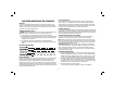
DC495 (FIG. 1, 7–10)
To remove shear head from motor, loosen the two back cap screws (G) using the
hex wrench (D) provided. Remove shear head (B) from the body by pulling head
firmly forward (Fig. 7). Slight twisting action may be required if head does not slide
off easily.
G
(BACK)
G (FRONT
O
FIG. 8
L
FIG. 7
B
D