
Instruction manual


10
To remove cutter blades from the shear head, completely loosen the two back cap
screws and remove shear head from motor unit. Loosen the tensioning screw (O)
1/2 turn. Completely loosen all three cap screws and remove head assembly. Turn
assembly over and remove top half of head and then remove the blades.
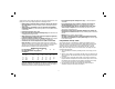
To replace blades, place lower jaw (P) onto two pins (R). Apply a thin layer of grease
from the packet (included) around the pin and on the top side of the blade. Place
upper jaw (Q) onto pin. Apply the rest of the grease provided onto the eccentric (L) on
the output shaft of the motor unit and into the area behind the upper moving blade in
the shear head.
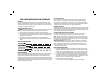
Install replacement washer (S), cone side up, over the pin on top of the moving
blade. Place top half of head back (T) onto bottom half (U), making sure to align the
pin to the hole. Reinstall all three cap screws (G) and nuts (V), but DO NOT tighten
completely.
Slide shear head back onto motor unit, making sure that the eccentric engages the
moving blade. Once the head is on the motor unit and aligned, tighten all three screws
and follow adjustment procedure below.
FIG. 9
S
P
Q
R
FIG. 10
V
G
P
Q
T
U
To ensure proper blade tension, tighten tensioning screw (O) by turning clockwise to
seat the blades. Next, loosen tensioning screw by turning counterclockwise slightly to
allow blade movement.
NOTE: The tensioning screw should be adjusted to correspond to material thickness.
Adjustment (Fig. 11, 12)
SWIVEL HEAD
WARNING: Turn unit off and disconnect battery pack before installing and
removing accessories, before adjusting or when making repairs. To prevent
inadvertant operation, lock the trigger switch when the tool is not in use and when
storing the tool.
To better accomodate safe cutting at any angle, the shear head can be repositioned by
loosening the three cap screws.
Once the screws are loosened, turn the shear head to the desired angle. Retighten the
three cap screws before installing battery pack.