
Instruction manual


7
b. Check to see if receptacle is connected to a light switch which turns power
off when you turn out the lights.
c. Move charger and battery pack to a location where the surrounding air
temperature is approximately 18° - 24°C (65°F - 75°F).
d. If charging problems persist, take the tool, battery pack and charger to your
local service center.
4. The battery pack should be recharged when it fails to produce sufficient power
on jobs which were easily done previously. DO NOT CONTINUE to use under
these conditions. Follow the charging procedure. You may also charge a partially
used pack whenever you desire with no adverse affect on the battery pack.
5. Under certain conditions, with the charger plugged into the power supply, the
exposed charging contacts inside the charger can be shorted by foreign material.
Foreign materials of a conductive nature such as, but not limited to, steel wool,
aluminum foil, or any buildup of metallic particles should be kept away from
charger cavities. Always unplug the charger from the power supply when there
is no battery pack in the cavity. Unplug charger before attempting to clean.
6. Do not freeze or immerse charger in water or any other liquid.
WARNING: Shock hazard. Don’t allow any liquid to get inside charger. Electric
shock may result. To facilitate the cooling of the battery pack after use, avoid placing
the charger or battery pack in a warm environment such as in a metal shed, or an
uninsulated trailer.
CAUTION: Never attempt to open the battery pack for any reason. If the plastic
housing of the battery pack breaks or cracks, return to a service center for recycling.
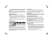
COMPONENTS (FIG. 1)
A. Trigger switch/variable speed switch
B. Swivel head shear
C. On/Lock-off control button
D. Hex wrench
E. Battery pack
F. Battery release buttons
Variable Speed Switch (Fig. 1)
To turn the tool ON, squeeze the trigger switch (A). To turn the tool OFF release the
trigger.
Your tool is equipped with a variable speed switch which enables you to select the
best speed for a particular application. The farther you squeeze the trigger, the faster
the tool will operate. Use lower speeds for cutting tight curves or following precise
guideline. Higher speeds are better for gradual curves and straight line cuts. For
maximum tool life, use lower speeds only for short periods of time.
On/Lock-Off Control Button (Fig. 1, 4)
An On/Lock control button (C) serves as a lock-off button. To select the ON position,
release the trigger switch and depress the control button on the right side of the tool,
as shown in
Figure 4. To select Locked/Off, depress the control button on the left side of the tool.
When changing the position of the control button, be sure the trigger is released.
FIG. 2
FIG. 3
F
Installing and Removing the Battery Pack (Fig. 3)
NOTE: Make sure your battery pack is fully charged.
WARNING: To prevent inadvertant operation, lock trigger switch before removing or
installing battery.
To install the battery pack into the tool handle, align the base of the tool with the
notch inside the tool’s handle and slide the battery pack firmly into the handle until
you hear the lock snap into place.