
Instruction manual


9
F
E
FIG. 4
Fuel Gauge Battery Packs (Fig. 2)
Some DEWALT battery packs include a fuel gauge which consists of three green LED
lights that indicate the level of charge remaining in the battery pack.
To actuate the fuel gauge, press and hold the fuel gauge button (K). A combination
of the three green LED lights will illuminate designating the level of charge left. When
the level of charge in the battery is below the usable limit, the fuel gauge will not
illuminate and the battery will need to be recharged.
NOTE: The fuel gauge is only an indication of the charge left on the battery pack.
It does not indicate tool functionality and is subject to variation based on product
components, temperature and end-user application.
For more information regarding fuel gauge battery packs, please call 1800 444 224
(Aust) or 0800 339 258 (NZ).
Variable Speed Trigger Switch (Fig. 2)
To turn the tool on, squeeze the trigger switch (A). To turn the tool off, release the
trigger switch. Your tool is equipped with a brake. The tool will stop when the trigger
switch is fully released. The variable speed switch enables you to select the best
speed for a particular application. The more you squeeze the trigger, the faster the
tool will operate. For maximum tool life, use variable speed only for starting holes or
fasteners.
NOTE: Continuous use in variable speed range is not recommended. It may damage
the switch and should be avoided.
Forward/Reverse Control Button (Fig. 2)
A forward/reverse control button (B) determines the direction of the tool and also
serves as a lock-off button. To select forward rotation, release the trigger switch (A)
and depress the forward/reverse control button on the right side of the tool. To select
reverse, release the trigger switch and depress the forward/reverse control button
on the left side of the tool. The center position of the control button locks the trigger
switch in the off position. When changing the position of the control button, be sure
the trigger is released.
Worklights (Fig. 2)
There are three worklights (G) located around the 6.35 mm (1/4") hex chuck (D). The
worklights are activated when the trigger switch is depressed. When the trigger is
released, the worklight will stay illuminated for up to 20 seconds.
NOTE: The worklights are for lighting the immediate work surface and are not
intended to be used as a flashlight.
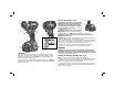
Speed Selector (Fig. 5)
J
FIG. 5
Your tool is equipped with a speed selector (J)
which allows you to select one of three speeds.
Select the speed based on the application and
control the speed of the tool using the variable
speed trigger switch (A).
Accessory Insertion and Release
(Fig. 6, 7)
NOTE: The tool accepts 6.35 mm (1/4") hex
accessories and 25.4 mm (1") bit tips only.
To install an accessory, fully insert the accessory into the 6.35 mm (1/4") hex
chuck (D). The accessory is locked into place (Fig. 6).
To remove an accessory, push on the accessory release button (C). Remove the
accessory then release the accessory release button (Fig. 7).