
operation manual

48
ENGLISH
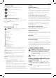
To Remove the Battery Pack from the Tool
1. Press the release button
11
and firmly pull the battery pack
out of the toolhandle.
2. Insert battery pack into the charger as described in the
charger section of thismanual.
Fuel Gauge Battery Packs (Fig. B)
Some
DeWALT
battery packs include a fuel gauge which
consists of three green LED lights that indicate the level of
charge remaining in the batterypack.
To actuate the fuel gauge, press and hold the fuel gauge button.
A combination of the three green LED lights will illuminate
designating the level of charge left. When the level of charge
in the battery is below the usable limit, the fuel gauge will not
illuminate and the battery will need to berecharged.
NOTE: The fuel gauge is only an indication of the charge left on
the battery pack. It does not indicate tool functionality and is
subject to variation based on product components, temperature
and end-userapplication.
Attaching Side Handle (Fig. C)
WARNING: Before using the tool, check that the handle is
tightenedsecurely.
Screw the side handle
5
tightly into one of the holes on either
side of the gear case. The side handle should always be used to
maintain control of the tool at alltimes.
Rotating the Gear Case (Fig. A)
To improve user comfort, the gear case will rotate 90° for
cuttingoperations.
1. Remove the four corner screws attaching the gear case to
motorhousing.
2. Without separating the gear case from motor housing,
rotate the gear case head to desiredposition.
NOTE: If the gear case and motor housing become separated
by more than 3.17 mm, the tool must be serviced and
re-assembled by a
DeWALT
service center. Failure to have the
tool serviced may motor and bearingfailure.
3. Reinstall screws to attach the gear case to the motor
housing. Tighten screws to 12.5 in.-lbs. torque.
Overtightening could cause screws tostrip.
Guards
CAUTION: Guards must be used with all grinding
wheels, cutting wheels, sanding flap discs, wire
brushes, and wire wheels. The tool may be used
without a guard only when sanding with conventional
sanding discs. Some applications may require purchasing
the correct guard from your local dealer or authorized
servicecentre.
NOTE: Edge grinding and cutting can be performed with Type
27 wheels designed and specified for this purpose; 6.35 mm
thick wheels are designed for surface grinding while thinner
Type 27 wheels need to be examined for the manufacturer's
label to see if they can be used for surface grinding or only
edge grinding/cutting. A Type 1 guard must be used for any
wheel where surface grinding is forbidden. Cutting can also be
performed by using a Type41 wheel and a Type 1guard.
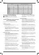
NOTE: See the Accessories Chart to select the proper guard /
accessorycombination.
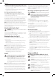
Mounting and Adjusting the One-Touch
TM
Guard (Fig. D)
WARNING: To reduce the risk of serious personal
injury, turn tool off and disconnect battery pack
before making any adjustments or removing/
installing attachments or accessories. An accidental
start-up can causeinjury.
Adjusting the Guard
For guard adjustment, the guard release lever
9
engages
one of the alignment holes
14
on the guard collar using a
ratchetingfeature.
The engaging face is slanted and will ride over to the
next alignment hole when guard is rotated in a clockwise
direction (spindle facing user) but self-locks in the anti-
clockwisedirection.
Mounting Guard (Fig. D)
1. Press the guard release lever
9
.
2. While holding the guard release lever open, align the lugs
12
on the guard with the slots
13
on the gearcase.
3. Keeping the guard release lever open, push the guard down
until the guard lugs engage and rotate them in the groove
on the gear case hub. Release the guard releaselever.
4. With the spindle facing the operator, rotate the guard
clockwise into the desired working position. Press and hold
the guard release lever
9
to rotate the guard in the anti-
clockwisedirection.
NOTE: The guard body should be positioned between
the spindle and the operator to provide maximum
operatorprotection.
The guard release lever should snap into one of the
alignment holes
14
on the guard collar. This ensures that
the guard issecure.
5. To remove the guard, follow steps 1–3 of these instructions
inreverse.
Flanges and Wheels
Mounting Non-Hubbed Wheels (Fig. E)
WARNING: Failure to properly seat the flanges and/or
wheel could result in serious injury (or damage to the tool
or wheel).
CAUTION: Included flanges must be used with depressed
centre Type 27 and Type 42 grinding wheels and
Type41 cutting wheels. See the Accessories Chart for
moreinformation.
WARNING: A closed, two-sided cutting wheel guard is
re quired when using cuttingwheels.
WARNING: Use of a damaged flange or guard or fail ure
to use proper flange and guard can re sult in injury due to
wheel breakage and wheel contact. See the Accessories
Chart for moreinformation.