
Use and Care Manual


ENGLISH
8
SAVE THESE INSTRUCTIONS FOR
FUTURE USE
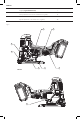
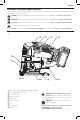
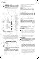
COMPONENTS (FIG. A)
WARNING: Never modify the power tool or any part
of it. Damage or personal injury couldresult.
Refer to Figure A at the beginning of this manual for a
complete list ofcomponents.
Intended Use
The DCS334 and DCS335 jig saws are designed for
professional cutting of wood, steel, aluminium, plastic and
ceramicmaterial.
DO NOT use under wet conditions or in presence of
flammable liquids orgases.
These jig saws are professional power tools. DO NOT let
children come into contact with the tool. Supervision is
required when inexperienced operators use thistool.
Lock-Off Button and Variable Speed
Trigger (Fig. A)
DCS334
To lock the variable speed trigger
1
, press the lock-off
button
2
. When the lock-off button is depressed to the lock
icon, the unit islocked.
Always lock the trigger switch when carrying or storing the
tool to eliminate unintentionalstarting.
To unlock the trigger switch, press the lock-off button.
When the lock-off button is depressed to the unlock icon,
the unit isunlocked.
NOTE: The lock-off button is colored red to indicate when
the switch is in its unlockedposition.
To start the DCS334 jig saw, squeeze the variable speed
trigger
1
.
To slow and stop the jig saw, release thetrigger.
As the trigger is pressed in, the strokes-per-minute continue
to increase up to the maximum speed of the tool. As the
trigger is released, the blade strokes-per-minutereduce.
NOTE: This tool has no provision to lock the switch in
the ON position, and should never be locked ON by any
othermeans.
On/Off Switch (Fig. A)
DCS335
CAUTION: Move the on/off switch
1
to the OFF
position before inserting the batterypack.
To start the DCS335 jig saw, move the on/off switch
1
to
the ON position. To turn the jig saw off, move the on/off
switch to the OFFposition.
ASSEMBLY AND ADJUSTMENTS
WARNING: To reduce the risk of serious personal
injury, turn unit off and remove the battery pack
before making any adjustments or removing/
installing attachments or accessories. An
accidental start-up can causeinjury.
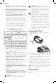
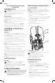
Blade Installation and Removal (Fig. D, J)
To Install a Blade
NOTE: These jig saws use only T-shank jig sawblades.
NOTE: When installing flush cutting blades, the anti-splinter
insert (
19
, Fig. J) must be removed and the shoe must to
be in the 0° positive stopposition.
1. Hold open the blade release latch
4
as shown in
FigureD.
2. Insert the T-shank blade into the clamp mechanism
12
while guiding the back of the blade into the groove of
the guide rollers
13
.
3. The T-shank should be completely inside the
clampmechanism.
4. Release the blade releaselatch.
13
12
4
Fig. D
To Remove a Blade
CAUTION: Do not touch used blades, they may be
hot. Personal injury mayresult.
1. Hold open the blade release latch
5
.
2. With a slight shake the blade will dropout.
3. Release the blade releaselatch.
Beveling the Shoe (Fig. E)
To Bevel the Shoe
1. Remove the dust extraction accessories if they are
mounted to the tool as the tool will not bevel if they are
attached. Refer to Dust Extractionsection.
2. Unlock the shoe by pulling the shoe bevel lever
8
to
theside.
3. Slide the shoe
7
forward to release it from the 0°
positive stopposition.
NOTE: The shoe can be beveled to the left or to the
right to a maximum of 45° in either direction. There are
visible detents at 15° and 30°.
4. Once the desired bevel angle is achieved, lock the shoe
in position: