INSTRUCTION MANUAL DCS355-XE 18V BRUSHLESS CORDLESS MULTI TOOL
Vibration total values (triax vector sum) determined according to EN 60745: Definitions: Safety Guidelines Vibration emission value ah ah = Uncertainty K = The definitions below describe the level of severity for each signal word. Please read the manual and pay attention to these symbols. DANGER: Indicates an imminently hazardous situation which, if not avoided, will result in death or serious injury.
SAVE ALL WARNINGS AND INSTRUCTIONS FOR FUTURE REFERENCE 3) PERSONAL SAFETY a) Stay alert, watch what you are doing and use common sense when operating a power tool. Do not use a power tool while you are tired or under the influence of drugs, alcohol or medication. A moment of inattention while operating power tools may result in serious personal injury. b) Use personal protective equipment. Always wear eye protection.
Electrical Safety d) Store idle power tools out of the reach of children and do not allow persons unfamiliar with the power tool or these instructions to operate the power tool. Power tools are dangerous in the hands of untrained users. e) Maintain power tools. Check for misalignment or binding of moving parts, breakage of parts and any other condition that may affect the power tool’s operation. If damaged, have the power tool repaired before use. Many accidents are caused by poorly maintained power tools.
min ..................minutes or DC.....direct current ...................Class I Construction (grounded) ...................Class II Construction (double insulated) …/min .............per minute BPM .................beats per minute RPM.................revolutions per minute sfpm ................
Important Safety Instructions for All Battery Chargers NOTE: Do not store the battery packs in a tool with the trigger switch locked on. Never tape the trigger switch in the ON position. WARNING: Fire hazard. Never attempt to open the battery pack for any reason. If the battery pack case is cracked or damaged, do not insert into the charger. Do not crush, drop or damage the battery pack. Do not use a battery pack or charger that has received a sharp blow, been dropped, run over or damaged in any way (e.g.
Indicator Light Operation • Do not place any object on top of the charger or place the charger on a soft surface that might block the ventilation slots and result in excessive internal heat. Place the charger in a position away from any heat source. The charger is ventilated through slots in the top and the bottom of the housing. • Do not operate the charger with a damaged cord or plug. • Do not operate the charger if it has received a sharp blow, been dropped or otherwise damaged in any way.
6. Foreign materials of a conductive nature such as, but not limited to, grinding dust, metal chips, steel wool, aluminum foil, or any buildup of metallic particles should be kept away from charger cavities. Always unplug the charger from the power supply when there is no battery pack in the cavity. Unplug the charger before attempting to clean. 7. Do not freeze or immerse the charger in water or any other liquid. WARNING: Shock hazard. Don’t allow any liquid to get inside the charger.
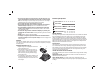
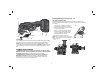
Installing/Removing Accessories (Fig. 3–5) FIG. 2 TOOL-FREE ACCESSORY CLAMP The DCS355 features a quick change accessory system. This allows for faster accessory changes without the need for wrenches or hex keys like other oscillating tool systems. 1. Grasp the tool and squeeze the accessory FIG. 3 clamping lever (C) as shown in Figure 3. 2. Clean any residual debris from the tool shaft and the accessory holder. 3.
Attaching the Cut/Depth Guide (Fig. 8–12) INSTALLING/REMOVING SANDING SHEETS (FIG. 6) A diamond shaped platen uses a hook and loop FIG. 6 adhesion system to attach the sanding sheets. The platen allows you to use it on large flat L surfaces and tight spots or corners. 1. Attach the sanding platen (K) as described under Installing/Removing Accessories. 2. Align the edges on the sanding sheet, with the edge of the sanding platen and press the sanding sheet (L) onto the platen. 3.
2. Adjust the length of the guide by pulling out or pushing inward to achieve the desired length as shown in Figure 12. 3. Secure the guide in place by turning the depth/cut adjustment knob (P) clockwise. To release the guide, turn the depth/cut adjustment knob counterclockwise. FIG.
Pushing the button to the left or right with the trigger depressed will lock the trigger in the depressed position. This allows for more comfort and control in extended use applications. Pressing the trigger switch again will release the lock out and the tool will turn off upon release of the trigger. LED Worklight (Fig. 18) The LED worklight (B) will activate any time the trigger is depressed and will remain on for 20 seconds after trigger is released. FIG. 16 FIG. 18 B A Variable Speed Trigger (Fig.
MAINTENANCE WARNING: To reduce the risk of serious personal injury, turn the tool off and disconnect the battery pack before making any adjustments or removing/installing attachments or accessories. An accidental start-up can cause injury. Lubrication Your power tool requires no additional lubrication. Cleaning WARNING: Blow dirt and dust out of all air vents with clean, dry air at least once a week. To minimize the risk of eye injury, always wear AS/NZS1337 approved eye protection when performing this.
DEWALT BATTERY AND CHARGER SYSTEMS Cat. Number Voltage Amp Hour DC9360 DE0240-XJ DW0242 DW0240 DC9096 DC9180 DCB180 DCB181 DCB182 DCB183 DCB185 DW9096 DE9095-XJ DC9091 DC9144 DCB140 DCB141 DCB142 DCB143 DCB145 DE9094 DE9091-XJ DW9091 DC9071 DE9071-XJ DE9074-XJ DW9050 DW9071 DW9072 DCB120 DCB123 DW9063 DW9062 DW9061 DW9048 DCB080 DW9057 DW9046 Chargers/Charge Time Output Nominal Battery 36 24 24 24 18 18 18 18 18 18 18 18 18 14.4 14.4 14.4 14.4 14.4 14.4 14.4 14.4 14.4 14.4 12 12 12 12 12 12 10.8 10.