
Use and Care Manual
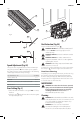

ENGLISH
10
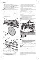
6. Use the hex wrench to turn the blade clamping screw
24
counter-clockwise toremove.
7. Remove the outer flange
25
and used blade
10
. Place
the new blade on the inner flange
26
.
8. Replace the outer flange
25
and blade clamping screw
24
. Turn the screw clockwise byhand.
NOTE: The direction of rotation of the saw blade and the
rotation of the track saw MUST be thesame.
9. Tighten the blade clamping screw firmly using the
hexwrench.
10. Release and turn the spindle lock lever
13
counter-
clockwise until itstops.
11. Move the track saw back to topposition.
12. Push the plunge trigger
1
forward, to take the saw out
of blade changemode.
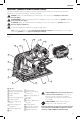
Fig. E
24
25
21
26
10
23
5/64”-1/8”
(2–3 mm)
22
21
5/64”-1/8”
(2–3 mm)
Adjusting the Riving Knife (Fig. A1, D, E)
For the correct adjustment of the riving knife
21
, refer
to FigureE. Adjust the clearance of the riving knife after
changing the saw blade or whenevernecessary.
1. Follow Changing the Saw Blade steps 1–5.
2. Loosen the riving knife adjustment screw
22
with a hex
wrench and set the riving knife as shown in FigureE.
3. Tighten the riving knife adjustment screw
22
.
4. Turn the spindle lock lever
13
counter-clockwise until
itstops.
5. Move the track saw back to topposition.
6. Push the plunge trigger
1
forward, to take the saw out
of blade changemode.
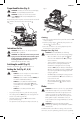
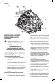
Depth of Cut Adjustment (Fig. F)
The cutting depth can be set at 0–2.3” (0–59 mm) without
guide rail attached; with the guide rail attached: 0–2.2”
(0–55 mm).
1. Loosen the depth adjustment knob
8
and move the
pointer to obtain the correct depth ofcut.
2. Tighten the depth adjustment knob
8
.
NOTE: For optimal results, allow the saw blade to protrude
from the workpiece by about 1/8” (3 mm) (Fig.F).
4
8
Fig. F
OPERATION
WARNING: To reduce the risk of serious personal
injury, turn unit off and remove the battery pack
before making any adjustments or removing/
installing attachments or accessories. An
accidental start-up can causeinjury.
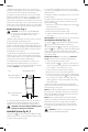
Installing and Removing the Battery Pack
(Fig. A1)
NOTE: For best results, make sure your battery pack is
fullycharged.
To install the battery pack
14
into the tool handle, align the
battery pack with the rails inside the tool’s handle and slide
it into the handle until the battery pack is firmly seated in
the tool and ensure that it does notdisengage.
To remove the battery pack from the tool, press the release
button
15
and firmly pull the battery pack out of the tool
handle. Insert it into the charger as described in the charger
section of thismanual.