
Use and Care Manual


ENGLISH
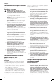
12
of kickback. Change blades when it is no longer easy to
push the saw through the cut, when the motor is straining,
or when excessive heat is built up in the blade. It is a
good practice to keep extra blades on hand so that sharp
blades are available for immediate use. Dull blades can be
sharpened in most areas; see SAWS-SHARPENING in the
yellow pages. Hardened gum on the blade can be removed
with kerosene, turpentine, or oven cleaner. Anti-stick coated
blades can be used in applications where excessive build-up
is encountered, such as pressure treated and greenlumber.
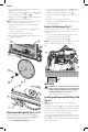
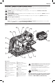
Blade Selection (Fig. I)
WARNING: To minimize the risk of kickback and
to ensure proper cutting, the blade selected must
be appropriate for the thickness of the riving
knifeprovided.
The blade supplied with this circular saw is the correct size
for the riving knife supplied with thesaw.
If a different blade is used, check the blade body (plate)
thickness and the blade kerf (cutting) width marked on the
blade or on the blade packaging. The riving knife thickness
must be greater than the body thickness and less than the
kerf width as shown in FigureI.
The riving knife provided with this saw is marked with its
thickness; .067" (1.7 mm). This riving knife should only be
used for blades with a 0.07" (1.8 mm) minimum kerf width
and 0.063" (1.6 mm) maximum bodythickness.
Your
DeWALT
track saw is designed for use with 6–1/2"
(165mm) diameter blades that have a 0.79" (20mm)
diameter bore. Blades must be rated for 6000 rpm operation
(or higher). DO NOT use any abrasivewheels.
Riving knife thickness
Kerf width (width of cut
made by the blade)
Body (or plate) thickness
of the blade
Fig. I
A combination blade is furnished with your saw and is an
excellent blade for all general ripping and crosscutting
operations. Use a fine-tooth blade for cuttingplywood.
WARNING: VISUALLY EXAMINE CARBIDE BLADES
BEFORE USE. REPLACE IFDAMAGED.
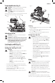
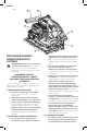
Guide Rail System (Fig. A1, J)
The guide rails
28
, which are available in different lengths,
allow for precise, clean cuts and simultaneously protect the
workpiece surface againstdamage.
In conjunction with additional accessories, exact angled
cuts, mitre cuts and fitting work can be completed with the
guide railsystem.
Securing the workpiece with clamps ensures a secure hold
and safeworking.
The guide clearance of the track saw must be very small
for best cutting results and can be set with the two rail
adjustment knobs
5
.
1. Release the screw inside the rail adjustment knobs
5
to
adjust theclearance.
2. Adjust the knob until saw locks onrail.
3. Rotate knob back until saw slideseasily.
4. Hold the rail adjustment knob in position and lock the
screwagain.
NOTE: ALWAYS readjust the system for use with otherrails.
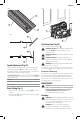
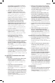
Anti-Splinter Guard (Fig. J, K)
The guide rail
28
is equipped with an anti-splinter guard
30
, which has to be trimmed before the first use.
The anti-splinter guard
30
is situated on each edge of the
guide rail (
28
, Fig. J). The purpose of this anti-splinter guard
is to provide the user with a visible blade cut line while
reducing the chipping that occurs along the workpiece cut
edge duringcutting.
IMPORTANT: ALWAYS read and follow the Guide Rail
System instructions before cutting the splinterguard!
1. Set the speed of the track saw to level7.
2. Place the guide rail
28
on a scrap piece of wood. Use a
clamp to ensure that the guide rail is securely attached
to the workpiece. This will ensureaccuracy.
3. Set the track saw on 13/64” (5 mm) cutdepth.
4. Place the saw on the rear end of the guiderail.
5. Turn the saw on, press it down to the set cutting depth
and cut the anti-splinter guard
30
along the full length
in one continuous operation. The edge of the anti-
splinter guard now corresponds exactly to the cutting
edge of theblade.
To trim the anti-splinter guard on the other side of the
guide rail, remove the saw from the rail and rotate the rail
180°. Repeat steps 1 through 4.
NOTE: If desired, the splinter guard can be bevelled to 45°,
then repeat steps 1 through 4. This allows one side of the
rail for cutting parallel cuts and the other side of the rail is
tuned in for 45° bevel cuts (Fig. K).
NOTE: If the anti-splinter guard is trimmed for parallel
cutting on both sides, then when the unit is bevelled, the
blade will not run true to the edge of the anti-splinter
guard. This is because the pivot point of the unit bevel
is not stationary and the blade moves out when the unit
isbevelled.
WARNING: To reduce the risk of injury, ALWAYS
secure the guide rail with aclamp.