
Operation Manual


ENGLISH
45
The hand-held radar scanner can map and analyze
up to a 3meter (9.8foot) section of wall.
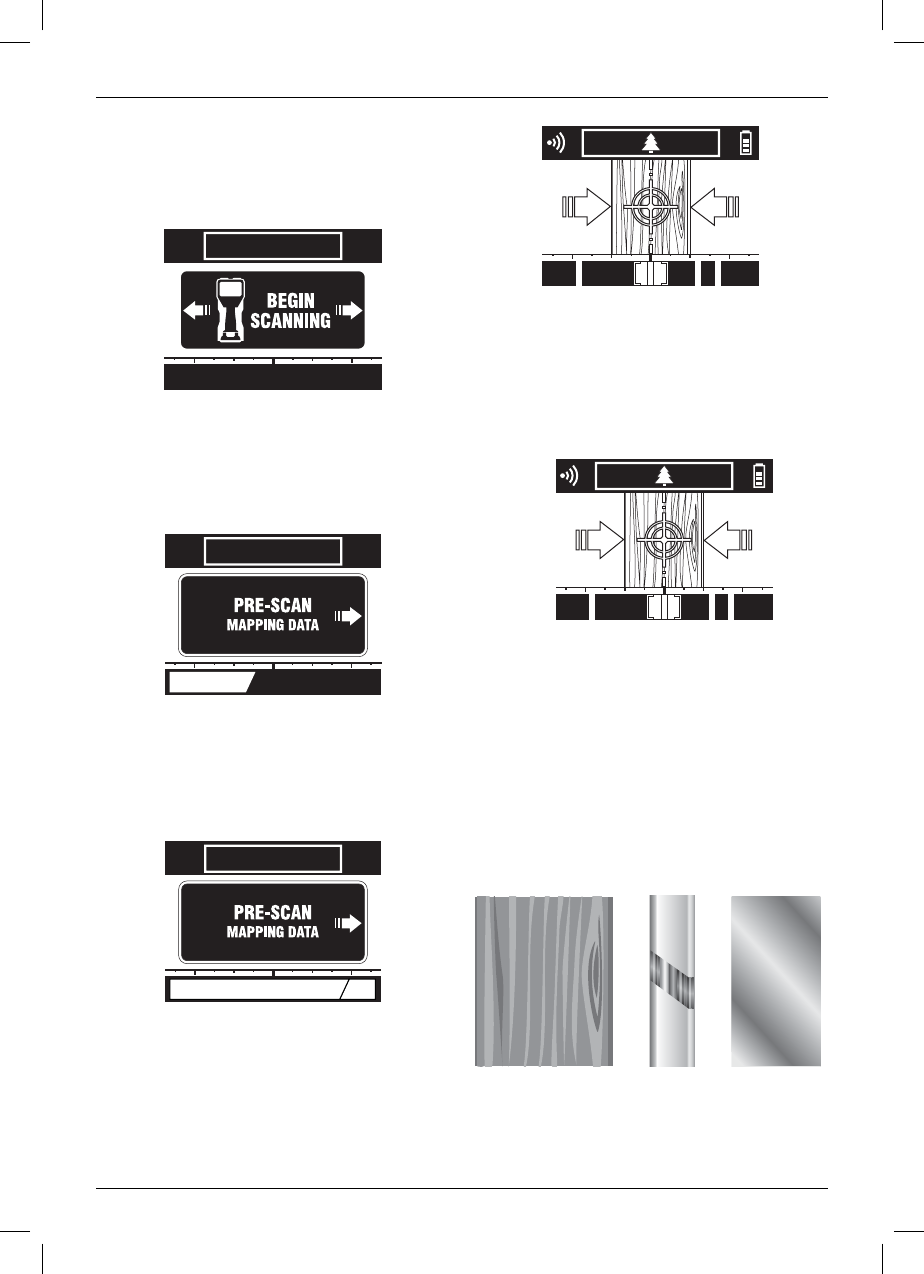
SCANNING PROCESS
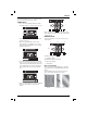
1. The screen below will indicate that the hand-
held radar scanner is ready to start a new scan.
2. Place the hand-held radar scanner on the wall
to start a new scan.
3. Move the hand-held radar scanner along
the wall surface in a straight line. The screen
below will appear indicating the pre-scan data
mapping is in process.
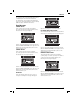
4. The hand-held radar scanner has a scannable
range of 3meters (9.8feet) of wall section. The
yellow memory bar will fill, indicating how much
of the available range is used. As the distance
limit is approached, the memory bar will turn
red.
5. Reverse scanning direction to read the mapped
data. The main viewing screen below will
appear.
Ensure that the wheels are in contact with the wall
surface during the entire pre-scan data mapping and
scanning passes.
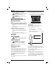
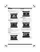
MAIN VIEWING SCREEN
The main viewing screen contains several sections
of information.
P
Q
R
O
S
O. Main Scanning Window
P. Confidence Meter
Q. Material Identification Window
R. Battery Fuel Gauge
S. Tracking Bar
Main Scanning Window
The main scanning window (O) will give a graphical
representation of the item identified below the wall
surface.
Items identified include wood, ferrous metal, non-
ferrous metal, plastic and live electric wires.
Wood Live Electric Ferrous Metal