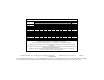
DEWALT Battery and Charger Systems Batt. Output Model# Volts DW0242 DW9096 DW9098 DW9099 DW9091 DW9094 DW9071 DW9072 DW9050 DW9061 DW9062 DW9048 DW9057 Chargers/Charge Time - Chargeurs/Durée de charge (Minutes) - Cargadores de baterías/Tiempo de carga (Minutos) 120 Volts DW9106 DW9118 DW9107 DW9108 DW9116 DW9117 DW911 DW0249 DW0246 24 X X X X X X X 60 60 18 X X X 60 60 20 60 X X 18 X X X 30 30 12 30 X X 18 X X X 45 45 15 45 X X 14.4 60 90 45 45 45 15 45 X X 14.
Questions? See us on the World Wide Web at www.dewalt.com INSTRUCTION MANUAL GUIDE D'UTILISATION MANUAL DE INSTRUCCIONES DW077 Rotary Laser Laser rotatif Láser rotativo INSTRUCTIVO DE OPERACIÓN, CENTROS DE SERVICIO Y PÓLIZA DE GARANTÍA. ADVERTENCIA: LÉASE ESTE INSTRUCTIVO ANTES DE USAR EL PRODUCTO.
1-800-4-DEWALT (1-800-433-9258) WARNING! Read and understand all instructions. Failure to follow all instructions listed below may result in electric shock, fire and/or serious personal injury. SAVE THESE INSTRUCTIONS SAFETY INSTRUCTIONS FOR LASERS • Do not operate the laser in explosive atmospheres, such as in the presence of flammable liquids, gases, or dust. Power tools create sparks which may ignite the dust or fumes. • Use the laser only with the specifically designated batteries.
English NOTE: This equipment has been tested and found to comply with the limits for a Class B digital device, pursuant to Part 15 of the FCC Rules. These limits are designed to provide reasonable protection against harmful interference in a residential installation. This equipment generates, uses and can radiate radio frequency energy and, if not installed and used in accordance with the instructions, may cause harmful interference to radio communications.
nails, screws, keys, etc. without battery cap. Without cap in place, battery could short circuit causing fire or burns or damage to battery. Battery Packs Your tool uses a 9.6, 12.0, 14.4 or an 18 Volt DEWALT battery pack. When ordering replacement battery packs, be sure to include catalog number and voltage: Extended Run-Time battery packs deliver 25% more run-time than standard battery packs. XR+ Extended Run-Time battery packs deliver 40% more run time than standard battery packs.
English • Before using battery charger, read all instructions and cautionary markings on battery charger, battery and product using battery. CAUTION:To reduce the risk of injury, charge only DEWALT nickel cadmium rechargeable batteries. Other types of batteries may burst causing personal injury and damage. CAUTION: Under certain conditions, with the charger plugged in to the power supply, the exposed charging contacts inside the charger can be shorted by foreign material.
CHARGERS Battery Perfomance Some chargers have a tune-up feature that optimizes battery pack performance. Your charger may provide Automatic Tune-Up™ Mode or manual (i.e., push button) Tune-Up™ mode. For information on this feature, please see the appropriate section below. Because batteries slowly lose their charge when they are not on the charger, the best place to keep your battery pack is on the charger at all times.
English continuously. The pack is fully charged and may be used at this time or left in the charger. 15 MINUTE CHARGERS 1. Plug the charger into an appropriate power outlet. The charger will beep twice, the red light will blink and go off. 2. Insert the battery pack into the charger, as shown in FIG. 1, making sure the pack is fully seated in the charger. The red light will blink and the charger will beep once indicating the charging process has started. 3.
CAUTION: Never attempt to open the battery pack for any reason. If the plastic housing of the battery pack breaks or cracks, return the battery pack to a service center for recycling. LASER OPERATION • Ensure that the battery is properly charged. If the “Power” LED light is flashing, the battery needs to be charged. • To extend battery life per charge, turn the laser off when it is not in use. • To ensure the accuracy of your work, check the laser calibration often.
English Installing and Removing the Battery Pack Control Panel A The laser is controled by the power button (E), the speed/rotation button (F), the scan mode button (G), and two arrows (H and I). The arrows control the movement of the laser head left and right or up and down depending on whether the laser is being used in the level mode or the plumb mode. Three indicator lights are on the control panel, power (J), X-axis leveling (K), and Y-axis leveling (L). TURNING THE LASER ON 1.
line up the laser with control marks. The remote allows one person to set up the laser. Using the Laser with a Wall Mount The DW077 Rotary Laser has been designed to work with an accessory Wall Mount (DW0770). It can be used for attaching the tool to track or celing angle (mould) and to aid in acoustical ceiling installation. Follow the directions below for using the wall mount. CAUTION: Before attaching the laser level to wall track or ceiling angle, be sure that the track or angle is properly secured. 1.
English 6. Once you have positioned the laser at the desired offset height, tighten the Rack “N Pinion locking knob to maintain the offset. 7. Using the base leveling knob (T) approximate a level position from the wall. CAUTION: Always use a ceiling wire hanger or equivalent material, in addition to the wall mount clamp, to help secure the laser level while mounting it to a wall. Thread the wire through the handle of the laser level. DO NOT thread the wire through the protective metal cage.
Target Card The DEWALT Rotary Laser Kit includes a Laser Target Card to aid in locating and marking the laser beam. The target card enhances the visibility of the laser beam as the beam crosses over the card. The card is marked with standard and metric scales. The laser beam passes through the red plastic and reflects off of the reflective tape on the reverse side. The magnets at the top of the card are designed to hold the target card to ceiling track or steel studs to determine plumb and level positions.
INDICATORS display icons audible signals English for use with non-rotating lasers but is compatible with most rotary red-beam or infra-red (invisible) beam lasers on the market. It can be set to indicate the location of the beam to either the nearest 1/8” or the nearest 1/25”. The detector gives both visual signals through the display window (B) and audio signals through the speaker (E) to indicate the location of the laser beam.
have centered the detector. For information about the display window indicators and the audible signal indicators, see the table titled “indicators”. 5. Use the marking notches (G) to accurately mark the position of the laser beam. MOUNTING ON A GRADE ROD 1. To secure your detector to a grade rod, first attach the detector to the clamp by pushing in on the clamp latch (N).
English Detector Service BEAM Except for batteries, there are no user serviceable parts in the Digital Laser Detector. Do not disassemble the unit. Unauthorized tampering with the laser detector will void all warranties. APPROX. 50 FT. Detector Troubleshooting THE DETECTOR WILL NOT TURN ON • Press and release the power/volume button. • Check to see that the battery is in place and in the proper position. • If the detector is very cold, allow it to warm up in a heated area. • Replace the 9 volt battery.
6. If the distance between the two marks is no more than 1/8" (3.2 mm), the laser is properly calibrated. 7. Repeat the above steps for the Y-axis by pointing the Y-axis towards the wall and then turning the laser 180˚ again. PLUMB ERROR CHECK 1. Using a standard plumb bob as a reference, mark the top and bottom of a wall (Be sure to mark the wall and not the floor & ceiling.) 2. Position the rotary laser securely on the floor approximately 3’ (1m) from the wall.
English In addition to the warranty, DEWALT tools are covered by our: 30 DAY NO RISK SATISFACTION GUARANTEE If you are not completely satisfied with the performance of your DEWALT heavy duty industrial tool, simply return it to the participating seller within 30 days for a full refund. Please return the complete unit, transportation prepaid. Proof of purchase may be required. FREE WARNING LABEL REPLACEMENT: If your warning labels become illegible or are missing, call 1-800-4-DEWALT for a free replacement.
SI VOUS AVEZ DES QUESTIONS OU VOULEZ NOUS FAIRE PART DE VOS COMMENTAIRES CONCERNANT CET OUTIL OU TOUT AUTRE OUTIL DeWALT, COMPOSEZ SANS FRAIS LE : 1 800 433-9258 AVERTISSEMENT : lire, comprendre et suivre toutes les directives précisées ci-dessous, y compris les consignes de sécurité, afin d’éviter les risques de choc électrique, d’incendie ou de blessure grave.
Français L’outil ne comprend aucune pièce interne destinée à être entretenue par l’utilisateur. Le fait de démonter le laser rotatif annulera toute garantie appuyant ce produit; on ne doit jamais modifier ce dernier de quelque manière que ce soit afin d’éviter d’entraîner des risques d’exposition aux rayonnements. • L’étiquette apposée sur l’outil peut afficher les symboles suivants : V ........................volts MW ....................milliwatts ................symbole d’avertissement du laser nm......
Importantes consignes de sécurité concernant le bloc-pile 19 Français Le bloc-pile n’est pas complètement chargé au moment de sa livraison! Avant de le charger, lire attentivement toutes les consignes de sécurité énumérées ci-dessous, ainsi que les remarques, les notes et les méthodes de chargement. LIRE TOUTES LES DIRECTIVES • Ne pas incinérer le bloc-pile, même s’il a subi des dommages importants ou s’il est usé complètement, car il pourrait exploser en présence de flammes.
Bloc-pile L’outil fonctionne sur un bloc-pile DEWALT de 9,6, de 12,0 de 14,4 ou de 18 volts. Lorsqu’on commande des bloc-piles de rechange, on doit indiquer le numéro de catalogue et la tension requise. Les blocs-piles à durée prolongée ordinaires et de type « XR+ » durent respectivement 25 % et 40 % plus longtemps que les blocs-piles standard. REMARQUE : l’outil peut fonctionner au moyen d’un bloc-pile standard ou à durée prolongée.
• Ne pas utiliser de rallonge à moins que cela ne soit absolument nécessaire, car l’usage d’une rallonge ayant une puissance inadéquate pourrait causer des risques d’incendie, de choc électrique ou d’électrocution. • Afin d’assurer la sécurité de l’utilisateur, la rallonge doit être de calibre AWG approprié. Plus le calibre est petit, plus la capacité est grande; autrement dit, une rallonge de calibre 16 est plus puissante qu’une rallonge de calibre 18.
Français chargeur pendant au moins huit heures, jusqu’à ce que le cycle décrit ci-dessous soit terminé. 1. Le voyant rouge clignotera continuellement, indiquant que le cycle de charge d’une heure est amorcé. 2. Une fois le cycle de rechargement terminé, le voyant restera allumé, indiquant que le bloc-pile est complètement rechargé; on peut alors le réutiliser. 3.
Dispositif de détection de piles chaudes ces cycles, il n’est complètement chargé que lorsque le voyant rouge reste allumé continuellement. On peut laisser le chargeur (avec un bloc-pile inséré) raccordé à une prise tant que le voyant rouge reste allumé; le chargeur maintient alors la charge du blocpile afin que ce dernier soit prêt à être utilisé. Un bloc-pile perd graduellement sa charge s’il n’est pas gardé dans le chargeur.
Français problème persiste, (4) retourner l’outil, le bloc-piles et le chargeur au centre de service de sa région. 4. Le bloc-piles doit être rechargé lorsqu’il ne produit pas suffisamment de courant pour permettre à l’utilisateur de travailler normalement. On doit CESSER de l’utiliser dans de telles conditions et suivre la méthode de chargement. On peut aussi charger en tout temps un bloc-piles partiellement déchargé sans nuire à son fonctionnement. 5.
ment prévu pour un bloc-pile de 9,6, de 12 ou de 14,4 volts ou pour un bloc-pile de 18 volts; aligner le logement avec les éléments de contact des piles (ces derniers doivent être orientés vers l’intérieur). 2. Glisser le bloc-pile fermement dans le laser rotatif jusqu’à ce qu’on entende un déclic indiquant qu’il est A bien enclenché. RETRAIT DU BLOC-PILE 1. Appuyer légèrement sur le bloc-pile, puis sur les boutons de dégagement et tirer fermeD ment le bloc-pile hors de son compartiment 2.
Français Installation sur trépied 1. Déposer le trépied sur une surface stable et le régler à la hauteur voulue. 2. S’assurer que le trépied qu’on prévoit utiliser est plus ou moins de niveau. Le laser se met automatiquement de niveau seulement lorsque le trépied est placé à ± 5 ºdu niveau approprié. Si le laser est trop hors de niveau, il émet un signal sonore lorsqu’il atteint sa limite de gammes de niveaux. Bien que le laser ne subisse aucun dommage, il ne fonctionne pas s’il n’est pas de niveau. 3.
MISE EN GARDE : lorsqu’on utilise un support mural, toujours accrocher le niveau laser au plafond au moyen du crochet prévu à cette fin ou d’un dispositif semblable afin de s’assurer qu’il est bien retenu au mur. Passer un fil à travers la poignée/cage métallique de protection. On peut aussi utiliser des vis pour assujettir l’outil directement au mur. Les trous (Q) prévus à cette fin sont situés sur le support mural, près des échelles de mesure. 4.
sur un rail de plafond ou sur un poteau en acier pour définir le niveau horizontal ou vertical. Lorsqu’on utilise la carte indicatrice de cibles, orienter le logo de DEWALT vers soi afin d’en assurer un rendement optimal. MISE EN GARDE : l’usage d’un accessoire non recommandé peut présenter un danger. N’utiliser que des accessoires DEWALT conçus pour être utilisés avec ce produit.
vent à faire pivoter l’aire de balayage dans l’une de ces directions. Les boutons pointant vers le haut et vers le bas ne fonctionnent que lorsque le laser est en mode de balayage. Le premier bouton sert à agrandir l’aire de balayage et le deuxième, à la réduire.
la fenêtre. Dans les deux cas, le détecteur donne une lecture « sans défaut » lorsque la précision du laser se trouve à l’intérieur de la gamme de précision indiquée (±3,2 mm ou ±1,02 mm, selon le cas), ou légèrement au-dessus ou en-dessous celle-ci. Enfoncer le bouton de mode de précision (D) une seule fois pour modifier le mode de précision. signaux audio INDICATEURS 1. Installer et placer le laser rotatif qu’on prévoit utiliser en suivant les directives du fabricant.
Guide de dépannage loquet de la bride (N), puis en faisant glisser les rails de la bride de retenue (O) autour du rail du détecteur (Q) afin d’enclencher le loquet de la bride (R) dans son orifice (R) situé sur le détecteur. 2. Ouvrir les mâchoires de la bride en tournant le bouton de serrage (S) vers la gauche. 3. Placer le détecteur laser à la hauteur voulue, puis tourner le bouton de serrage vers la droite afin de bien serrer la bride de retenue sur le tube jaugeur. 4.
Français ENTRETIEN DU LASER trat d’entretien gratuit d’un an offert par DEWALT comprend deux étalonnages gratuits. 5. Après chaque utilisation, ranger le laser dans le coffret fourni à cette fin. 6. Ne pas ranger le laser dans le coffret s’il est mouillé. Si tel est le cas, le laisser sécher à l’air et essuyer les pièces externes au moyen d’un chiffon sec et doux. 7. Ne pas ranger le laser à des températures inférieures à -18 ºC (0 ºF) ou supérieures à 40 ºC (105 ºF). 1.
Réparations 3. Mettre l’outil en marche, sans le régler en mode de rotation. 4. Orienter manuellement le faisceau vers le mur le plus éloigné et en marquer le centre sur la surface du mur. REMARQUE : diriger le faisceau sur une surface blanche pour faciliter le marquage. 5.
SI TIENE ALGUNA PREGUNTA O COMENTARIO RELACIONADO A ESTA O A CUALQUIER OTRA HERRAMIENTA DeWALT, LLAME GRATIS AL: 1-800-4-DEWALT (1-800-433-9258) ¡ADVERTENCIA! Por favor lea detenidamente el manual de instrucciones antes de utilizar el producto; el no cumplir con las instrucciones puede resultar en choque eléctrico, incendio y (o) serias lesiones personales.
¡ADVERTENCIA! NO DESARME EL LÁSER ROTATIVO. El interior de esta herramienta no contiene partes de utilidad para el consumidor. El desarmar el láser rotativo anulará de inmediato las garantías del producto. A fin de evitar cualquier exposición peligrosa a la radiación del láser, no altere ni modifique este producto de ninguna manera. • La etiqueta de su herramienta puede incluir los siguientes símbolos. V..........................voltios mW ....................mili vatio ................
• Para mayor asistencia, por favor consulte con el distribuidor del producto o con un técnico de radios y televisores. Los aparatos digitales clase B cumplen con las normas canadienses ICES-003. Español Instrucciones de seguridad sobre las baterías tóxico.
voltaje. Los paquetes de baterías de tiempo de ejecución prolongado proveen 25% más tiempo de operación que los paquetes de baterías estándar. Los paquetes de baterías XR+ de tiempo de ejecución prolongado brindan 40% más tiempo de operación que los paquetes estándar. NOTA: esta herramienta aceptará paquetes de baterías estándar o de tiempo de ejecución prolongado.
• • • • Español • las baterías han sido diseñados específicamente para funcionar juntos. A fin de reducir cualquier riesgo de incendio, choque eléctrico o electrocución, no utilice este cargador para cargar baterías que no sean las baterías recargables DEWALT. Cuando desconecte el cargador de la toma de corriente, sujete el enchufe y hale con cuidado; no tire del cable. Asegúrese de acomodar el cable de manera que nadie lo hale, se tropiece ni se enrede.
FUNCIONAMIENTO DEL MODO TUNE-UP™ MANUAL El modo Tune-Up™ manual compensa o mantiene equilibradas las pilas individuales de las baterías en espacio de ocho horas para brindar máximo rendimiento. Las baterías deberán ser ajustadas después de cada diez a veinte ciclos de carga / descarga o cuando no proporcionen el rendimiento apropiado. 1. Para ajustar las baterías, introdúzcalas en el cargador como de costumbre. Una luz roja parpadeará continuamente indicando que el ciclo de carga de una hora ha comenzado.
Español Indicadores de falla 3. Las baterías se cargarán completamente en espacio de una hora y la luz roja se encenderá para indicar la finalización del ciclo de carga. Las baterías se pueden utilizar o pueden permanecer en el cargador. CARGADORES DE 15 MINUTOS 1. Enchufe el cargador en una toma de corriente apropiada. El cargador producirá un tono dos veces, la luz roja parpadeará y luego se apagará. 2. Introduzca las baterías en el cargador (figura 1) y asegúrese que estén bien asentadas.
Baterías débiles 5. Bajo ciertas condiciones, con el cargador conectado a la toma de corriente, los contactos de carga expuestos dentro del cargador pueden hacer contacto entre sí debido a algún material externo. Los materiales externos de naturaleza conductora tales como, pero sin limitarse a ellos, el alambre de acero, el papel aluminio o cualquier tipo de partícula metálica, deben conservarse alejados de las cavidades del cargador.
• Siempre trace el centro de la línea o del punto láser. Si traza marcas diferentes a intervalos sobre el haz, las mediciones no serán precisas. • A fin de abarcar mayor distancia y lograr mejor precisión, instale el láser en el centro del área de trabajo. • Cuando instale el láser en el montaje de pared o sobre el trípode asegúrelo bien. • En las aplicaciones interiores, la rotación lenta del cabezal del láser produce un haz de luz luminoso y la rotación rápida produce un haz de luz visiblemente sólido.
ALIGNEMENT VERTICAL nivelación del eje-Y (L). COMO ACTIVAR EL LÁSER 1. Introduzca las baterías completamente cargadas en el compartimiento apropiado de la placa del adaptador y asegúrese que encajen bien. 2. Para activar el láser, presione el interruptor de encendido y apagado (E). El diodo del láser se encenderá y brillará la luz del diodo emisor de luz (J). Si el láser está desnivelado, las luces de nivelación tanto del eje-X como la del eje-Y (K y L), parpadearán hasta que el láser se haya nivelado.
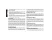
P Q R S O T P que la mordaza esté bien afianzada en el carril antes de proceder. PRECAUCIÓN: Siempre utilice un gancho de suspensión de alambre o de material semejante, además de la mordaza del montaje, para asegurar el nivel láser. Pase el alambre por el mango del nivel láser pero NUNCA a través del marco de metal que protege la unidad. Como medida de refuerzo, se puede utilizar tornillos para fijar el montaje directamente a la pared.
escalas del láser. El blanco de tarjeta DEWALT está marcado a 1 1/2", de manera que resulta más fácil ajustar el desplazamiento del láser a 1 1/2" menor que el ángulo de la pared. 6. Una vez que ajuste el láser a la altura de desplazamiento deseada, apriete la perilla de fijación de piñón y cremallera para no perder el desplazamiento. 7. Utilice la perilla de nivelación de la base (T) para establecer una posición de nivel desde la pared.
que éste pasa sobre la tarjeta. La tarjeta tiene escalas de medición métrica y estándar. El rayo láser pasa a través de la tarjeta roja de plástico y se refleja en la cinta adhesiva lustrosa por el revés. La tarjeta tiene magnetos en la para fijarla a los carriles de los cielos rasos o a los postes de acero a fin de establecer posiciones de nivel y plomada. Para obtener mejores resultados cuando utilice el blanco de tarjeta, asegúrese que la inscripción DEWALT señale hacia usted.
El detector digital de láser se puede utilizar con o sin la ayuda de una mordaza; la mordaza permite fijar el detector a las varillas de nivelar, miras de nivelación, soportes o postes.
aproximadamente a ± 1/8". Presione el botón (D) una vez para cambiar el modo de precisión. la mordaza (O) alrededor del riel del detector (Q) hasta que el seguro (R) de la mordaza enganche adentro del orificio del seguro (R) del detector, 2. Para abrir la mordaza, gire la perilla (S) hacia la izquierda. 3. Ajuste el detector a la altura deseada y gire la perilla de la mordaza hacia la derecha para asegurar la mordaza a la varilla. 4.
2. La guarda flexible de goma se puede limpiar con un paño de algodón humedecido que no despida pelusa. UTILICE AGUA SOLAMENTE — NO utilice limpiadores ni solventes. Espere que la unidad esté seca antes de almacenarla. 3. A fin de conservar la precisión de su trabajo, verifique la calibración del láser con frecuencia. Consulte la sección sobre calibración del láser señalada anteriormente en este manual. 4.
NOTA: El orientar el punto hacia una superficie blanca facilita trazar las marcas. 5. Gire la unidad 180˚ completos de manera que el eje-X señale en dirección contraria a la pared. Oriente el punto manualmente (o utilice las flechas derecha/izquierda del control remoto) de manera que el punto se encuentre lo más cerca posible a la primera marca de elevación. Marque nuevamente el centro del punto en la pared. 6.
organizaciones autorizadas. Estas organizaciones prestan servicio a las herramientas DEWALT y emplean siempre refacciones legitimas DEWALT. • Cuando el producto hubiese sido alterado o reparado por personas distintas a las enlistadas al final de este certificado. Anexo encontrará una relación de sucursales de servicio de fábrica, centros de servicio autorizados y franquiciados en la República Mexicana, donde podrá hacer efectiva su garantía y adquirir partes, refacciones y accesorios originales.
Español PARA REPARACION Y SERVICIO DE SUS HERRAMIENTAS ELECTRICAS FAVOR DE DIRIGIRSE AL CENTRO DE SERVICIO MAS CERCANO AGUASCALIENTES Av. de los Maestros 903 Col. España 449-913-38-01 CAMPECHE Av. Gobernadores 345 Col. Santa Ana 981-811-34-90 CHIAPAS 5 Norte Oriente 460 Col. Centro 961-600-02-87 CHIHUAHUA Av. Universidad 2903 Col. Universidad 614-413-64-04 DURANGO Av. 20 de Noviembre 2004 Ote Col. Centro 618-818-80-77 GUANAJUATO 1 Mayo 482 Col. Centro 462-626-79-22 GUADALAJARA Av. Vallarta 4901-a Col.