
Instruction manual


8
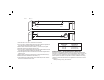
hole (H), allowing the wall mount to be attached to any surface with a nail or screw.
Once the wall mount is secured, its steel plate provides a surface to which the
magnetic pivot bracket can be attached. The position of the laser can then be
fine-tuned by sliding the pivot bracket up or down on the wall mount.
LEVELING THE LASERS
As long as the DW086-XE and DW087-XE lasers are properly calibrated, the lasers
are self-leveling. Each laser is calibrated at the factory to find level as long as it is
positioned on a flat surface within average ± 4° of level. No manual adjustments must
be made.
MAINTENANCE
• To maintain the accuracy of your work, check the laser often to make sure it is
properly calibrated. See Field Calibration Check.
• Calibration checks and other maintenance repairs may be performed by DEWALT
service centers.
• When not in use, store the laser in the kit box provided. Do not store your laser at
temperatures below -20˚C (-5˚F) or above 60˚C (140˚F).
• Do not store your laser in the kit box if the laser is wet. The laser should be dried
first with a soft dry cloth.
Cleaning
Exterior plastic parts may be cleaned with a damp cloth. Although these parts are
solvent resistant, NEVER use solvents. Use a soft, dry cloth to remove moisture from
the tool before storage.
Field Calibration Check
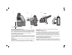
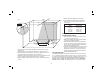
CHECKING ACCURACY – HORIZONTAL BEAM, SCAN DIRECTION (FIG. 6)
Checking the horizontal scan calibration of the laser requires two walls 9 m (30')
apart. It is important to conduct a calibration check using a distance no shorter than
the distance of the applications for which the tool will be used.
1. Attach the laser to a wall using its pivot bracket. Make sure the laser is facing
straight ahead.
FIG. 6
b
Step 1
a
Step 2
45˚
90˚
Step 3
Step 4
Step 2
Step 3
2. Turn on the laser’s horizontal beam and pivot the laser approximately 45˚
so that the right-most end of the laser line is striking the opposing wall at
a distance of at least 9 m (30'). Mark the center of the beam (a).
3. Pivot the laser approximately 90˚ to bring the left-most end of the laser line
around to the mark made in Step 2. Mark the center of the beam (b).
4. Measure the vertical distance between the marks.
5. If the measurement is greater than the values shown below, the laser must be
serviced at an authorized service center.
Distance Allowable Distance
Between Walls Between Marks
9 m (0') 3.0 mm (1/8")
12 m (40') 4.0 mm (5/32")
15 m (50') 5.0 mm (7/32")
CHECKING ACCURACY – HORIZONTAL BEAM, PITCH DIRECTION (FIG. 7)
Checking the horizontal pitch calibration of the laser requires a single wall at least 9 m
(30') long. It is important to conduct a calibration check using a distance no shorter
than the distance of the applications for which the tool will be used.