
Technical data


ENGLISH
21 en - 4
A5
33 Work piece clamp
A6
34 Dustbag
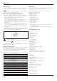
Assembly
Prior to assembly always unplug the tool.
Unpacking (fig. B)
• Remove the saw from the packing material carefully using the carrying
handle (9).
• Press down the operating handle (1) and pull out the lock down pin
(28), as shown.
• Gently release the downward pressure and allow the arm to rise to its
full height.
Bench mounting (fig. C)
• Holes (8) are provided in all four feet to facilitate bench mounting.
Two different sized holes are provided to accommodate different sizes
of bolts. Use either hole; it is not necessary to use both. Always mount
your saw firmly to prevent movement. To enhance the portability, the
tool can be mounted to a piece of 12.5 mm or thicker plywood which
can then be clamped to your work support or moved to other job sites
and reclamped.
• When mounting your saw to a piece of plywood, make sure that the
mounting screws do not protrude from the bottom of the wood.
The plywood must sit flush on the work support. When clamping the
saw to any work surface, clamp only on the clamping bosses where
the mounting screw holes are located. Clamping at any other point will
interfere with the proper operation of the saw.
• To prevent binding and inaccuracy, be sure the mounting surface is not
warped or otherwise uneven. If the saw rocks on the surface, place a
thin piece of material under one saw foot until the saw is firm on the
mounting surface.
Mounting the saw blade (fig. D1 - D5)
• Depress the head lock up release lever (10) to release the lower guard
(2), then raise the lower guard as far as possible.
• Using the Torx bit (36) in the handgrip end of the supplied blade
spanner (21), loosen the guard bracket screw (37) sufficiently to allow
the angled corner piece (38) to pass between the head of the screw
and the guard. This will allow the guard bracket (39) to be raised
enough to permit access to the blade locking screw (40).
• With the lower guard held in the raised position by the guard bracket
scew (37) depress the spindle lock button (15) with one hand, then use
the supplied blade spanner (21) in the other hand to loosen the left-
hand threaded blade screw (40) by turning clockwise.
To use the spindle lock, press the button as shown and rotate
the spindle by hand until you feel the lock engage. Continue to
hold the lock button in to keep the spindle from turning.
• Remove the blade locking screw (40) and the outside arbor collar (41).
• Install the saw blade (42) onto the shoulder (43) provided on the inside
arbor collar (44), making sure that the teeth at the bottom edge of the
blade are pointing toward the back of the saw (away from the operator).
• Replace the outer arbor collar (41).
• Tighten the blade locking screw (40) by turning counter-clockwise while
holding the spindle lock engaged with your other hand.
• Move the guard bracket (39) down until the angled corner piece (38) is
below the head of the guard bracket screw (37).
• Tighten the guard bracket screw.
Never press the spindle lock while the blade is rotating.
Be sure to hold the guard bracket down and firmly tighten the
guard bracket screw after installing the blade.
Adjustment
Prior to adjustment always unplug the tool.
Your mitre saw was accurately adjusted at the factory. If readjustment due
to shipping and handling or any other reason is required, follow the steps
below to adjust your saw. Once made, these adjustments should remain
accurate.
Checking and adjusting the blade to the fence (fig. E1 - E4)
• Loosen the mitre clamp knob (4) and squeeze the mitre latch (5)
upwards to release the mitre arm (47).
• Swing the mitre arm until the latch locates it at the 0° mitre position. Do
not tighten the clamp knob.
• Pull down the head until the blade just enters the saw kerf (46).
• Place a square (48) against the left side (7) of the fence and blade (42)
(fig. E3).
Do not touch the tips of the blade teeth with the square.
If adjustment is required, proceed as follows:
• Loosen the three screws (49) and move the scale/mitre arm assembly
left or right until the blade is at 90° to the fence as measured with the
square.
• Retighten the three screws (49). Pay no attention to the reading of the
mitre pointer at this point.
Adjusting the mitre pointer (fig. E1, E2 & F)
• Loosen the mitre clamp knob (4) and squeeze the mitre latch (5) to
release the mitre arm (47).
• Move the saw arm to set the mitre pointer (50) to the zero position,
as shown in fig. F.
• With the mitre clamp knob loose, allow the mitre latch to snap into
place as you rotate the mitre arm past zero.
• Observe the pointer (50) and mitre scale (6) through the viewing opening
(51). If the pointer does not indicate exactly zero, loosen the screw (53),
move the plastic moulding (52) to read 0° and tighten the screw.
Checking and adjusting the blade to the table (fig. G1 - G3)
• Loosen the bevel clamp handle (17).
• Press the mitre arm to the right to ensure it is fully vertical and tighten
the bevel clamp handle.
• Pull down the head until the blade just enters the saw kerf (46).
• Place a set square (48) on the table and up against the blade (42) (fig. G2).
Do not touch the tips of the blade teeth with the square.
If adjustment is required, proceed as follows:
• Loosen the bevel clamp handle (17) and turn the vertical position
adjustment stop screw (30) in or out until the blade is at 90° to the
table as measured with the square.
• If the bevel pointer (54) does not indicate zero on the bevel scale (12),
loosen the screw (55) that secures the pointer and move the pointer as
necessary.