
Technical data


en - 7 24
ENGLISH
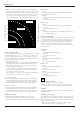
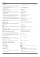
• Example: To make a 4 sided box with 25° exterior angles (angle “A“)
(fig. P2), use the upper right arc. Find 25° on the arc scale. Follow the
horizontal intersecting line to either side to get the mitre angle setting
on the saw (23°). Likewise follow the vertical intersecting line to the top
or bottom to get the bevel angle setting on the saw (40°). Always try
cuts on a few scrap pieces of wood to verify the settings on the saw.
Vernier scale (fig. Q1 - Q3)
Your saw is equipped with a vernier scale for added precision. For settings
that require partial degrees (
1
/4°,
1
/2°,
3
/4°), the vernier scale allows you to
accurately set mitre angles to the nearest
1
/4° (15 minutes). To use the
vernier scale follow the steps listed below. As an example, assume that
the angle you want to mitre is 24
1
/4° right.
• Switch off the mitre saw.
• Set the mitre angle to the nearest whole degree desired by aligning the
centre mark in the vernier scale, shown in fig. Q1, with the whole
degree number etched in the mitre scale. Examine fig. Q2 closely;
the setting shown is 24° right mitre.
• To set the additional
1
/4°, squeeze the mitre arm lock and carefully
move the arm to the right until the %1° vernier mark aligns with the
closest degree mark on the mitre scale.
In this example, the closest degree mark on the mitre scale happens to
be 25°. Fig. Q3 shows a setting of 24
1
/4° right mitre.
When mitring to the right:
• increase the mitre angle by moving the arm to align the appropriate
vernier mark with the closest mark on the mitre scale to the right.
• decrease the mitre angle by moving the arm to align the appropriate
vernier mark with the closest mark on the mitre scale to the left.
When mitring to the left:
• increase the mitre angle by moving the arm to align the appropriate
vernier mark with the closest mark on the mitre scale to the left.
• decrease the mitre angle by moving the arm to align the appropriate
vernier mark with the closest mark on the mitre scale to the right.
Cutting base mouldings
The cutting of base moulding is performed at a 45° bevel angle.
• Always make a dry run without power before making any cuts.
• All cuts are made with the back of the moulding laying flat on the saw.
Inside corner
- Left side
• Position the moulding with top of the moulding against the fence.
• Save the left side of the cut.
- Right side
• Position the moulding with the bottom of the moulding against
the fence.
• Save the left side of the cut.
Outside corner
- Left side
• Position the moulding with the bottom of the moulding against
the fence.
• Save the right side of the cut.
- Right side
• Position the moulding with top of the moulding against the fence.
• Save the right side of the cut.
Cutting crown mouldings
The cutting of crown moulding is performed in a compound mitre. In order
to achieve extreme accuracy, your saw has pre-set angle positions at
31.62° mitre and 33.85° bevel. These settings are for standard crown
mouldings with 52° angles at the top and 38° angles at the bottom.
• Make test cuts using scrap material before doing the final cuts.
• All cuts are made in a left bevel and with the back of the moulding
against the base.
Inside corner
- Left side
• Top of the moulding against the fence.
• Mitre right.
• Save the left side of the cut.
- Right side
• Bottom of the moulding against the fence.
• Mitre left.
• Save the left side of the cut.
Outside corner
- Left side
• Bottom of the moulding against the fence.
• Mitre left.
• Save the left side of the cut.
- Right side
• Top of the moulding against the fence.
• Mitre right.
• Save the right side of the cut.
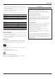
Dust extraction (fig. A2 & A6)
• Fit the dustbag (34) onto the dust spout (20).
• Whenever possible, connect a dust extraction device designed in
accordance with the relevant regulations regarding dust emission.
Saw blades
To obtain the stated cutting capacities, always use 305 mm saw blades
with 30 mm arbor holes.
Cutting non-ferrous metals
When cutting non-ferrous metals, the machine is only to be used in the
mitre saw mode. We recommend that bevel and compound mitre cuts
should not be performed in non-ferrous metals. The machine is not to be
used for cutting ferrous metals.
• Always use a material clamp when cutting non-ferrous metals.
Make sure that the workpiece is clamped securely.
0 5 10 15 20 25 30 35 40 45
0 5 10 15 20 25 30 35 40 45
5
10
15
20
25
30
35
40
45
5
10
15
20
25
30
35
40
5
10
15
20
25
30
35
40
45
50
55
60
65
70
75
80
85
5
10
15
20
25
30
35
40
45
50
55
60
65
70
75
80
85
5
10
15
20
25
30
35
40
45
50
55
60
65
70
75
80
85
SET THIS BEVEL ANGLE ON SAW
SET THIS MITER ANGLE ON SAW
ANGLE OF SIDE OF BOX (ANGLE"A")
SQUARE BOX
6 SIDED BOX
8 SIDED BOX