www. .
Copyright DEWALT 2
10 11 14 13 12 39 3 6 8 7 5 4 2 1 9 A1 14 15 16 22 20 17 18 19 21 A2 1
25 26 24 27 23 22 A3 35 30 31 28 A4 2 29 33 32 34 A5
36 37 29 A6 A7 38 X A8 B 3
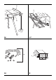
46 47 48 49 18 C2 C1 50 20 2 E1 56 23 55 52 D 4 E2
60 58 59 57 F1 F2 62 63 64 22 8 60 61 67 65 F3 G1 7 66 62 4 52 68 70 70 69 G2 H 66 62 22 71 I1 I2 5
72 7 J1 J2 73 74 K1 22 K2 77 76 75 16 12 2 L2 L1 16 62 16 3-8 mm M 6 N 76 25 20
26 79 80 81 78 O Q 77 P R 17 S T 82 U 81 V1 7
85 85 84 V2 W 8 83 V3
ENGLI SH FLIP-OVER SAW DW743N Congratulations! You have chosen a DEWALT tool. Years of experience, thorough product development and innovation make DEWALT one of the most reliable partners for professional power tool users. The vibration emission level given in this information sheet has been measured in accordance with a standardised test given in EN 61029 and may be used to compare one tool with another. It may be used for a preliminary assessment of exposure.
EN GL I S H 13. Do not overreach. Keep proper footing and balance at all times. 14. Maintain tools with care. Horst Grossmann Vice President Engineering and Product Development DEWALT, Richard-Klinger-Straße 11, D-65510, Idstein, Germany 01.01.2010 Safety Instructions WARNING! When using electric tools basic safety precautions should always be followed to reduce the risk of fire, electric shock and personal injury including the following.
ENGLI SH – gloves for handling saw blades and rough material. Saw blades should be carried in a holder wherever practicable. • Refrain from removing any cut-offs or other parts of the work piece from the cutting area while the saw is running and the saw head is not in the rest position. • Replace the table insert when worn. • Replace the table when the slot in the table is too wide. • Do not use cracked or damaged saw blades. • Do not use any abrasive discs.
EN GL I S H • Always keep the push stick in its place when not in use. Do not use the riving knife when using the machine in the mitre saw mode. Make sure that the riving knife is secured in the upper rest position (fig. A2). • During transportation make sure that the upper part of the saw blade is covered, e.g. by the guard. Additional Safety Rules for Table Saws Carrying point • Rebating, slotting or grooving is not allowed. • Always use the push stick. Never cut workpiece smaller than 30 mm.
ENGLI SH 19 Foot Electrical Safety 20 Table locking device The electric motor has been designed for one voltage only. Always check that the power supply corresponds to the voltage on the rating plate. 21 Saw table retention bracket 22 Bevel clamp handle BENCH SAW MODE A3 22 Bevel clamp handle 23 Height adjuster 24 Bench saw table This machine is of Class I construction; therefore earthed (grounded) connection is required.
EN GL I S H Mounting the Machine to the Workbench (fig. C2) With the legs removed, the machine is suitable for placement on a workbench. To ensure a safe operation, the machine has to be fixed to the workbench and mounted with bolts 8 mm diameter by 80 mm long. ASSEMBLY FOR MITRE SAW MODE Mounting the Under-table Guard (fig. D) The under-table guard (50) is fitted to the top of the bench saw table. • Place the two hooks on the left of the guard into the oblong slots on the left of the blade slot (52).
ENGLI SH WARNING: Always make a trial cut in a piece of waste wood, to check for accuracy. WARNING: Never use your saw in bench saw mode without the upper guard correctly fitted. Adjusting the Fence (fig. J1, J2) Mounting and Adjusting the Parallel Fence (fig. O) The moveable part of the left side of the fence can be adjusted to provide maximum support of the workpiece near the blade, while allowing the saw to bevel to a full 45° left. The sliding distance is limited by stops in both directions.
EN GL I S H • Ensure the material to be sawn is firmly secured in place. • Apply only a gentle pressure to the tool and do not exert side pressure on the saw blade. • Avoid overloading. Ensure the machine is placed to satisfy your ergonomic conditions in terms of table height and stability. The machine site shall be chosen so that the operator has a good overview and enough free surrounding space around the machine that allows handling of the workpiece without any restrictions.
ENGLI SH • Set the blade height and angle. • Insert the slide bar (83) of the mitre fence into the groove (84) provided in the left-hand side of the table (fig. V2). • Loosen the mitre locking knob (85) and rotate the fence to set the scale to the required angle (fig. V3). • Tighten the mitre locking knob (85). • Place the workpiece against the flat surface of the mitre fence. Switch on and, holding the workpiece firmly, slide the fence along the groove to take the workpiece into the blade.
EN GL I S H • Slightly oil the rotating table bearing surface where it slides on the lip of the fixed table at regular intervals. • Clean the parts subject to accumulation of sawdust and chips periodically with a dry brush. Cleaning WARNING: Blow dirt and dust out of the main housing with dry air as often as dirt is seen collecting in and around the air vents. Wear approved eye protection and approved dust mask when performing this procedure.
19
20
21
Belgique et Luxembourg België en Luxemburg Black & Decker - DEWALT Nieuwlandlaan 7, IZ Aarschot B156 B-3200 Aarschot Tel: +32 (0)015 - 15 47 9211 Fax: +32 (0)015 - 15 47 9210 www.dewalt.be Danmark DEWALT Sluseholmen 2-4 2450 København SV Tlf: 70201511 Fax: 70224910 www.dewalt.dk Deutschland DEWALT Richard-Klinger-Straße 65510 Idstein Tel: 06126-21-1 Fax: 06126-21-2770 www.dewalt.de Ελλάς Black & Decker (Hellas) S.A.