DEWALT Industrial Tool Co., 701 East Joppa Road, Baltimore, MD 21286 (JAN03) Form No. 615104-00 Copyright © 2002, 2003 DW818, DW821, DW824, DW827 The following are trademarks for one or more DEWALT power tools: the yellow and black color scheme; the “D” shaped air intake grill; the array of pyramids on the handgrip; the kit box configuration; and the array of lozenge-shaped humps on the surface of the tool.
Questions? See us on the World Wide Web at www.dewalt.com INSTRUCTION MANUAL GUIDE D'UTILISATION MANUAL DE INSTRUCCIONES INSTRUCTIVO DE OPERACIÓN, CENTROS DE SERVICIO Y PÓLIZA DE GARANTÍA. ADVERTENCIA: LÉASE ESTE INSTRUCTIVO ANTES DE USAR EL PRODUCTO.
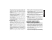
English SAVE THESE INSTRUCTIONS WARNING! Read and understand all instructions. Failure to follow all instructions listed below may result in electric shock, fire, and/or serious personal injury. GENERAL SAFETY INSTRUCTIONS • • • WORK AREA • • • Keep your work area clean and well lit. Cluttered benches and dark areas invite accidents. Do not operate power tools in explosive atmospheres, such as in the presence of flammable liquids, gases, or dust.
• • • • • • SERVICE • • TOOL USE AND CARE • • • • • Use clamps or other practical way to secure and support the workpiece to a stable platform. Holding the work by hand or against your body is unstable and may lead to loss of control. Do not force tool. Use the correct tool for your application. The correct tool will do the job better and safer at the rate for which it is designed. Do not use tool if switch does not turn it on or off.
English or its own cord. Contact with a “live” wire will make exposed metal parts of the tool “live” and shock the operator. • Before using, inspect recommended accessory for cracks or flaws. If such a crack or flaw is evident, discard the accessory. The accessory should also be inspected whenever you think the tool may have been dropped. Flaws may cause wheel breakage. • In operation, avoid bouncing the wheel or giving it rough treatment.
FIG. 1 INTRODUCTION A B FIG. 3 FIG. 2 B E FIG. 5 FIG. 4 ASSEMBLY CAUTION: Turn off and unplug the tool before making any adjustments or removing or installing attachments or accessories. Before reconnecting the tool, depress and release the rear part of the switch to ensure that the tool is off. F G FIG. 7 2. Push the guard down until the guard lugs engage and rotate freely in the B groove on the gear case. 3. With the guard latch (FIG.
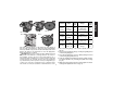
English FIG. 8 F FIG. 9 B 4. Rotate the spindle by hand while pressing the spindle lock button until the spindle locks, preventing the spindle from rotating. (FIG. 14). 5. Firmly tighten the threaded flange with the supplied spanner wrench (FIG. 15). H E E Mounting Grinding Wheels and Sanding Flap Discs Using Matching Flanges (FIG. 12-15) CAUTION: Do not tighten adjustment screw with guard latch in open position. Undetectable damage to the guard or the mounting hub may result.
FIG. 14 FIG.
English Mounting Backing Pads and Sanding Flap Discs 4. To stop the tool while operating in continuous mode, press the rear part of the switch and release. NOTE: To reduce unexpected tool movement, do not switch the tool on or off while under load conditions. Allow the grinder to run up to full speed before touching the work surface. Lift the tool from the surface before turning the tool off. Allow the tool to stop rotating before putting it down.
Precautions To Take When Sanding Paint 1. Sanding of lead based paint is NOT RECOMMENDED due to the difficulty of controlling the contaminated dust. The greatest danger of lead poisoning is to children and pregnant women. 2. Since it is difficult to identify whether or not a paint contains lead without a chemical analysis, we recommend the following precautions when sanding any paint: PERSONAL SAFETY a.
English MAINTENANCE Cleaning CAUTION: The use of any other accessory not recommended for use with this tool could be hazardous. Blowing dust and grit out of the motor housing using compressed air is a necessary regular maintenance procedure. Dust and grit containing metal particles often accumulate on interior surfaces and could create an electrical shock hazard if not frequently cleaned out. ALWAYS WEAR SAFETY GLASSES.
CONSERVER CES DIRECTIVES • AVERTISSEMENT! Lire et comprendre toutes les directives, car le non-respect des directives suivantes pourrait entraîner un risque de choc électrique, d’incendie ou de blessures graves. • ZONE DE TRAVAIL • • • Garder la zone de travail propre et bien éclairée; les établis encombrés et les endroits sombres sont propices aux accidents.
Français Calibre minimal des cordons de rallonge Tension Longueur totale du cordon en meters 120 V De 0 à 7 De 7 à 15 De 15 à 30 De 30 à 45 240 V De 0 à 7 De 7à 15 De 15 à 39 De 30 à 45 Intensité (A) Au Au Calibre moyen de fil moins plus 0 - 6 18 16 16 14 6 - 10 18 16 14 12 10 - 12 16 16 14 12 12 - 16 14 12 Non recommandé • • • • • médicaments, car un moment d’inattention pourrait entraîner des blessures graves. Porter des vêtements appropriés; ne pas porter de vêtements amples ni de bijoux.
ENTRETIEN • • L’outil doit être entretenu par le personnel qualifié seulement; toute maintenance effectuée par une personne non qualifiée pourrait entraîner des risques de blessure. Lors de l’entretien, n’utiliser que des pièces de rechange identiques et suivre les directives de la section «Entretien» du présent guide afin de prévenir les risques de choc électrique ou de blessure.
INTRODUCTION Composants Français • l’arsenic et le chrome dans le bois de sciage ayant subi un traitement chimique (comme de l’arséniate de cuivre et de chrome). Le risque associé à de telles expositions peut varier selon la fréquence avec laquelle on effectue ces travaux. Pour réduire l’exposition à de tels produits, il faut travailler dans un endroit bien aéré et utiliser l’équipement de sécurité approprié tel un masque anti-poussière spécialement conçu pour filtrer les particules microscopiques.
ASSEMBLAGE Fixation et retrait du dispositif de protection (fig. 6 et 7) F FIG. 9 B H E E 4. Fermer le mécanisme de verrouillage afin de fixer solidement le dispositif de protection au carter d’engrenage (fig. 7E or fig. 9E). REMARQUE : le dispositif de protection est réglé en usine en fonction du diamètre du moyeu de la broche. S’il s’avère nécessaire, après un certain temps, de le régler de nouveau, on doit suivre les étapes suivantes. Mettre le mécanisme de verrouillage en position fermée (fig.
Fixation et utilisation de meules abrasives ou de coupe-bordures (fig. 11 à 13) Français Fixation de la meule ou des disques souples de ponçage au moyen d’une bride à moyeu déporté (fig. 11 et 13 à 15) Des meules abrasives conçues spécialement pour la coupe et des coupe-bordures conçus spécialement pour le meulage des bords sont vendus séparément chez les dépositaires locaux ou aux centres de service autorisés.
à moyeu déporté de 15,2 cm (6 po) de diamètre (modèle DW827 seulement) doivent être installés uniquement avec des brides à moyeu déporté. Se reporter au tableau indiqué ci-dessous pour sélectionner la bride et le dispositif de protection qui convient à la meule utilisée. MISE EN GARDE : les meules abrasives et les coupe-bordures peuvent se briser s’ils sont pliés ou tordus lorsqu'on effectue des travaux de tronçonnage ou de meulage profond.
Fixation d’une meule à moyeu REMARQUE : pour empêcher l’outil de bouger de façon inattendue, ne pas le mettre en position de marche ou d’arrêt lorsqu’il est sous des conditions de charge; le laisser atteindre sa vitesse maximale avant de le mettre en contact avec la surface à meuler, et le soulever complètement avant de l’arrêter. Laisser l’outil s’arrêter complètement avant de le déposer. On peut visser une meule à moyeu directement sur la broche de la meuleuse, sans avoir à utiliser de brides.
lisse. Si on appuie seulement sur le bord extérieur du disque contre la pièce, le ponçage sera irrégulier et inégal, et l’outil sera difficile à maîtriser. Mesures de précaution concernant le ponçage de peinture 1. Le ponçage de peintures à base de plomb n’est PAS RECOMMANDÉ puisqu’il est trop difficile de maîtriser la poussière contaminée. Les enfants et les femmes enceintes courent le plus grand risque d’intoxication par le plomb. 2.
Balais de moteur doit se protéger en orientant l’ouverture du FIG. 21 dispositif de protection vers une surface quelconque. Seul le bord de la meule (et non sa partie inférieure ni supérieure) doit entrer en contact avec la surface à meuler. On risque de briser la meule si on y exerce une pression latérale. On peut utiliser une meule no 1 pour couper des bords. Consulter le guide d’utilisation fourni avec le dispositif de protection no 1 afin d’obtenir les directives appropriées.
Français En plus de la présente garantie, la GARANTIE SANS RISQUE DE 30 JOURS EN CAS DE NONSATISFACTION s’applique également aux outils DEWALT. Si l’acheteur n’est pas entièrement satisfait du rendement de l’outil industriel de service intensif DEWALT, celui-ci peut le retourner au vendeur participant dans les 30 jours pour obtenir un remboursement intégral. Retourner l’outil au complet en payant le transport à l’avance; une preuve d’achat peut être requise.
CONSERVE ESTAS INSTRUCCIONES ¡ADVERTENCIA! Lea y comprenda todas las instrucciones. No seguir las instrucciones listadas a continuación puede resultar en un choque eléctrico, incendio y(o) lesiones personales graves. • INSTRUCCIONES GENERALES DE SEGURIDAD ÁREA DE TRABAJO • • Español • • Conserve su área de trabajo limpia y bien iluminada. Las bancas amontonadas y las zonas oscuras propician los accidentes.
Calibre mínimo para cordones de extensión Volts Longitud total del cordón en metros 120V 0-7.5 7.6-15.2 15.3-30,4 30.4-45.7 240V 0-15.2 15.3-30.4 30,5-60.8 60.9-121.2 AMPERAJE en la placa de identificación Más No más Calibre AWG de de 0 6 18 16 16 14 6 10 18 16 14 12 10 12 16 16 14 12 12 16 14 12 No recomendado • Utilice equipo de seguridad. Siempre utilice protección en los ojos.
• Solamente use accesorios que el fabricante recomiende para su modelo de herramienta. Los accesorios que estén diseñados para una herramienta, pueden volverse peligrosos cuando se emplean con otra. • Antes de usar los accesorios recomendados, revíselos siempre en busca de cuarteaduras o defectos. Descártelos si tienen un desperfecto de esta clase. Deberá revisar, del mismo modo, los accesorios cuando sospeche que la unidad ha caído.
INTRODUCCIÓN • Plomo de pinturas con base de plomo. • Sílice cristalino de cemento, ladrillos y otros productos de albañil ería. • Arsénico y cromo de madera tratada químicamente (CCA). El riesgo originado por estas exposiciones varía de acuerdo con la frecuencia con que efectúes trabajos de este tipo. Para reducir la exposición a estos químicos: trabaje en áreas bien ventiladas y con equipo de seguridad aprobado, como las máscaras contra polvo diseñadas especialmente para filtrar partículas microscópicas.
FIG. 8 PRECAUCION: Apague y desconecte la herramienta antes de hacer cualquier ajuste o antes de instalar acoplamientos o accesorios. Antes de conectar nuevamente la herramienta, presione y suelte la parte trasera del conmutador para asegurarse que la herramienta está apagada. ENSAMBLAJE Instalación y remoción de la guarda (Figs. 6-7) FIG. 9 B H E E FIG. 6 PRECAUCION: Desconecte la herramienta antes de instalar o retirar la guarda.
FIG. 12 FIG. 11 5. Apriete con firmeza la arandela con cuerda con la llave que se le proporciona (FIG. 15). Montaje de piedras de esmeril y discos para lijar con arandelas apareadas (Figs. 12-15) FIG. 13 FIG. 14 Las piedras de esmeril están a su disposición como accesorios opcionales. Antes de instalar una piedra de esmeril, desconecte la herramienta de la toma de corriente. 1. Coloque la arandela de respaldo en la flecha de la esmeriladora (FIG. 11). 2. Coloque el disco contra la arandela.
Español do, pueden utilizarse con arandelas planas apareadas o con arandelas de centro hendido, si es que son menores a 127 mm (5") de diámetro. Los discos de orilla de 152 mm (6") de centro hendido (únicamente para el DW827) deben montarse únicamente con arandelas de centro hendido. Consulte la tabla a continuación para seleccionar la arandela y la guarda adecuadas para su disco.
Instalación de cepillos y las ruedas copa y ruedas de alambre NOTA: Para reducir movimientos inesperados de la herramienta, no encienda o apague la herramienta bajo condiciones de carga. Permita que la esmeriladora alcance la velocidad máxima antes de hacer contacto con la superficie de trabajo. Levante la unidad de la superficie antes de apagarla. Permita que la herramienta deje de girar antes de bajarla.
SEGURIDAD AMBIENTAL a. La pintura debe removerse de manera que se minimice la cantidad generada de polvo. b. Se deben sellar los accesos a las áreas en donde se está removiendo pintura con hojas de plástico cuyo espesor mínimo sea de 0.1 mm. c. El lijado se debe realizar de manera que se reduzca la salida de polvo de pintura fuera del área de trabajo. LIMPIEZA Y DESECHO a. Todas las superficies en el área de trabajo deben aspirarse y limpiarse diariamente mientras dure el lijado.
El corte de bordes se puede efectuar únicamente con piedras tipo 27 diseñadas específicamente para este propósito. Protéjase a sí mismo durante el corte de bordes dirigiendo el lado abierto de la guarda hacia la superficie. Los discos de esmerilado y corte de bordes deben hacer contacto con la superficie de trabajo únicamente en la orilla del disco, no en la parte superior o inferior de éste. La presión lateral en el disco puede romperlo. Los discos tipo 1 pueden utilizarse para corte de bordes.
Póliza de Garantía Anexo encontrará una relación de sucursales de servicio de fábrica, centros de servicio autorizados y franquiciados en la República Mexicana, donde podrá hacer efectiva su garantía y adquirir partes, refacciones y accesorios originales. Español IDENTIFICACIÓN DEL PRODUCTO: Sello o firma del Distribuidor. Nombre del producto: __________ Mod./Cat.: _____________ Marca: _____________________ Núm.
Información Tecnica DW818/DW821 Tensión de alimentación: Consumo de corriente: Frecuencia de Alimentación: Rotación sin carga: 120 V AC/DC ( 7,8 A 50/60 Hz 11,000/min ) Información Tecnica DW824 Tensión de alimentación: Consumo de corriente: Consumo de corriente: Frecuencia de Alimentación: Rotación sin carga: 120 V AC/DC ( 120 VAC-10 A 120 VDC-8 A 50/60 Hz 11,000/min ) Información Tecnica DW827 Tensión de alimentación: Consumo de corriente: Consumo de corriente: Frecuencia de Alimentación: Rotación s