
User Manual


8
ENGLISH
MAINTENANCE
Your power tool has been designed to operate over a long
period of time with a minimum of maintenance. Continuous
satisfactory operation depends upon proper tool care and
regularcleaning.
WARNING: To reduce the risk of serious personal
injury, turn tool off and disconnect tool from power
source before making any adjustments or removing/
installing attachments or accessories. An accidental
start‑up can causeinjury.
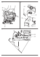
Rip/Circle Cutting (Fig.G, H)
Ripping and circle cutting without a pencil line is easily done with
the rip fence / circle guide (not included; available at extracost).
Using the screw supplied with the accessory guide, position and
thread the screw into the shoe to clamp the fencesecurely.
When ripping, slide the rip fence under the screw from either
side of the saw. Set the cross bar at desired distance from blade
and tighten screw. For ripping, the cross bar should be down and
against the straight edge of theworkpiece.
When circle cutting, adjust rip fence so that distance from blade
to hole in fence arm is at the desired radius and tighten screw.
Place saw so that hole in fence arm is over center of circle to be
cut (drill hole for blade or cut inward from edge of material to
get blade into position). When saw is properly positioned, drive
a small nail through hole in fence arm. Using rip fence as a pivot
arm, begin cutting circle. For circle cutting, the cross bar should
beup.
Hints for Optimum Use
Sawing laminates
As the saw blade cuts on the upward stroke, splintering may
occur on the surface closest to the shoeplate.
Use a fine‑tooth sawblade.
Saw from the back surface of theworkpiece.
To minimize splintering, clamp a piece of scrap wood or
hardboard to both sides of the workpiece and saw through
thissandwich.
Sawing metal
• Be aware that sawing metal takes much more time than
sawingwood.
• Use a saw blade suitable for sawingmetal.
• When cutting thin metal, clamp a piece of scrap wood to the
back surface of the workpiece and cut through thissandwich.
• Spread a film of oil along the intended line of cut for easier
operation and longer blade life. For cutting aluminum,
kerosene ispreferred.
To attach shoe sleeve, place the front of the shoe
6
into the
front of the shoe sleeve and lower the jig saw as shown in
FigureF. The shoe sleeve will click securely onto the rear of
theshoe.
To remove shoe sleeve, grasp the sleeve from the bottom at the
two rear tabs and pull down and away from theshoe.
Removable Shoe Sleeve (Fig.F)
The non‑marring shoe sleeve
5
should be used when cutting
surfaces that scratch easily, such as laminate, veneer, or
paint. It can also be used to protect the shoe surface during
transportation andstorage.
Cutting Action – Orbital or Straight (Fig.A)
WARNING: Check that the tool is not locked ON before
connecting it to a power supply. If the trigger switch is
locked on when the tool is connected to the power supply,
it will start immediately. Damage to your tool or personal
injury mayresult.
This jig saw is equipped with four cutting actions, three orbital
and one straight. Orbital action has a more aggressive blade
motion and is designed for cutting in soft materials like wood
or plastic. Orbital action provides a faster cut, but with a less
smooth cut across the material. In orbital action, the blade
moves forward during the cutting stroke in addition to the up
and downmotion.
NOTE: Metal or hardwoods should never be cut in orbitalaction.
Setting the Pendulum Stroke
1. Move the pendulum stroke selectorr
9
between the four
cutting positions: 0, 1, 2, and3.
2. Position 0is straightcutting.
3. Positions 1, 2, and 3are orbitalcutting.
The aggressiveness of the cut increases as the lever is adjusted
from one to three, with three being the most aggressivecut.
Variable Speed Control (Fig.A, E)
WARNING: If the tool is operated continuously at low
speeds for a long time, the motor will get overload and
heatedup.
A speed control dial
8
is located on the trigger for the DWE249
and on the top of the saw for the DWE349. The speed increases
as the dial is turned from a low speed setting of 1to a high
speed setting of 6.
Refer to the table to select the proper speed for the workpiece
to be cut. However, the appropriate speed may differ with the
type or thickness of the workpiece. In general, higher speeds
will allow you to cut workpieces faster but the service life of the
blade will bereduced.
Material Variable Speed Control Setting
Wood 5‑6
Stainless steel 3‑4
Mild steel 3‑6
Aluminum 3‑6
Plastics 1‑4
• For continuous operation, squeeze the trigger switch then
depress the lock‑on button
2
. Once lock‑on button is
depressed, release the triggerswitch.
• To switch the tool off, release the trigger switch. To switch
the tool off, when in continuous operation, squeeze the
trigger and the lock willdisengage.