
Product Manual
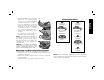
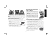

3. With the guard latch open, rotate the
I
J
FIG. 7
guard into the desired working
position that provides maximum
protection to the user as shown.
4. Close the guard latch to secure the
guard on the gear case. You should
be unable to rotate the guard by
hand when the latch is closed. Do
not operate the grinder with a loose
guard or the guard latch in open
position.
5. To remove the guard, follow the
procedure above in reverse order.
NOTE: The guard is pre-adjusted to
the diameter of the gear case hub at
the factory. If, after a period of time,
the guard becomes loose, tighten the
adjusting screw (J) with clamp in the
closed position.
NOTICE: Do not tighten the adjusting
screw with the guard latch in open
position. Undetectable damage to the
guard or the mounting hub may result.
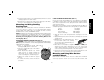
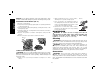
Mounting and Removing Hubbed Wheels
Hubbed wheels install directly on the 5/8"–11 threaded spindle.
1. Thread the wheel on the spindle by hand, seating the wheel
against the soft mount.
2. Depress the spindle lock button and use a wrench to tighten the
hub of the wheel.
3. Reverse the above procedure to remove the wheel.
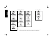
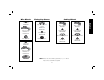
soft mount
445928-01
Type 27 guard
D284937 7"
D284939 9"
backing flange
54339-00
non-hubbed sanding
flap disc
clamp nut
22191-00
Sanding Flap Discs
soft mount
445928-01
Type 27 guard
D284937 7"
D284939 9"
hubbed sanding
flap disc
NOTE: Wheel size must match guard size; i.e., a new 7" wheel may
not be used with a 9" guard. The bottom surface of wheel must be
inside the bend of the guard lip.
English
11