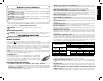
IF YOU SHOULD EXPERIENCE A PROBLEM WITH YOUR DEWALT PURCHASE, Before returning this product call 1-800-4-DEWALT CALL 1-800-4-DEWALT IN MOST CASES, A DEWALT REPRESENTATIVE CAN RESOLVE YOUR PROBLEM OVER THE PHONE. IF YOU HAVE A SUGGESTION OR COMMENT, GIVE US A CALL. YOUR FEEDBACK IS VITAL TO THE SUCCESS OF DEWALT’S QUALITY IMPROVEMENT PROGRAM. Questions? Visit us at www.dewalt.com Des questions ? Rendez nous visite à www.dewalt.com ¿Tiene preguntas? Visítenos en www.dewalt.
The definitions below describe the level of severity for each signal word. Please read the manual and pay attention to these symbols. DANGER: Indicates an imminently hazardous situation which, if not avoided, will result in death or serious injury. WARNING: Indicates a potentially hazardous situation which, if not avoided, could result in death or serious injury. CAUTION: Indicates a potentially hazardous situation which, if not avoided, may result in minor or moderate injury.
English • • • • • • • • • • • • metal prongs when unplugging or plugging in the cord. An accidental start-up can cause injury. REDUCE THE RISK OF UNINTENTIONAL STARTING. Make sure that the switch is in the “OFF” position before plugging in the power cord. In the event of a power failure, move the switch to the “OFF” position. An accidental start-up can cause injury. Do not plug into or unplug from power source with wet hands. USE RECOMMENDED ACCESSORIES.
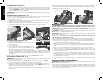
KICKBACKS Kickbacks can cause serious injury. A kickback occurs when a part of the workpiece binds between the saw blade and the rip fence, or other fixed object, and rises from the table and is thrown toward the operator. Kickbacks can be avoided by attention to the following conditions. How to Avoid Them and Protect Yourself from Possible Injury a. Use the blade guard with splitter, or use the riving knife whenever possible. b. Be certain that the rip fence is parallel to the saw blade. c.
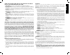
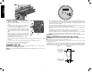
English WARNING: Use of this tool can generate and/or disperse dust, which may cause serious and permanent respiratory or other injury. Always use NIOSH/OSHA approved respiratory protection appropriate for the dust exposure. Direct particles away from face and body. FIG. 2 R 15 A 21-7/8" (556 mm) X 26-3/8" (669 mm) 30° L&R 0° to 45°L 10" (254 mm) 3-1/8" (79 mm) 2-1/4" (57 mm) 4800 Unpacking (Fig.
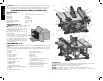
WARNING: Shock Hazard. To reduce the risk of serious personal injury, turn unit off and disconnect machine from power source before attempting to move it, change accessories or make any adjustments. An accidental start-up can cause injury. THIS SAW SHOULD BE ASSEMBLED IN THE FOLLOWING ORDER: (FIG, 2, 4) 1. Make sure blade is installed correctly and arbor nut is tight. Use wrenches (U) stored on the tool. Refer to Figure 3. 2. Install and lock throat plate (Q).
English With power disconnected, operate the blade tilt and height adjustments through the extremes of travel and ensure the blade guard assembly clears the blade in all operations and that the anti-kickback assembly is functioning. TO REMOVE THE THROAT PLATE 1. Remove the throat plate (Q) by turning the cam lock knob (CC) 1/4 turn counterclockwise 2. Using finger hole (DD) on the plate, pull throat plate up and forward to expose the inside of the saw. DO NOT operate the saw without the throat plate.
BEVEL STOP AND POINTER ADJUSTMENT (FIG. 19, 20) 1. Raise the blade fully by rotating the blade height FIG. 19 adjustment wheel (F) clockwise until it stops. 2. Unlock the bevel lock lever (G) by pushing it up and to the right. Loosen the bevel stop screw (NN). 3. Place a square flat against the table top and against the blade between teeth, as shown in Figure 20. Ensure the bevel lock lever is in its unlocked, or up, position. NN 4.
FIG. 25 DD English FIG. 23 U ALIGNING RIVING KNIFE TO BLADE (FIG. 24) 1. Remove the throat plate. Refer to Remove Throat FIG. 24 Plate under Assembly. 2. Raise the blade to full depth of cut and 0° bevel PP angle. 3. Locate the three small set screws (PP) adjacent to the riving knife lock knob (QQ). These screws will be used to adjust the riving knife position. 4. Lay a straight edge on the table against two blade QQ tips. The riving knife should not touch the straight edge.
The riving knife provided with this saw is marked as follows (Fig. 27): OPERATION FIG. 27 All DEWALT blade body thickness and kerf widths are provided at www.dewalt.com. If a different blade is used and the body thickness FIG. 28 and kerf width dimensions are not provided, use the following procedure to determine the correct riving knife thickness: 1. Measure the body thickness of the blade. 2. Make a shallow cut in scrap material and measure the kerf width. 3. Select the riving knife (Fig. 28). 4.
English On-Off Switch (Fig. 29) FIG. 29 X H Y WORK SUPPORT EXTENSION/NARROW RIPPING FENCE The table saw is equipped with a narrow ripping fence that also supports work that extends beyond the saw table. To use the narrow ripping fence in the work support position, rotate it from its stored position as shown in Figure 31, and slide the pins into the lower sets of slots (A3) on both ends of the fence.
WARNING: Use a push stick to feed the workpiece if there is 2–6" (51–152 mm) between the fence and the blade. Use a narrow ripping fence feature and push block to feed the workpiece if there is 2" (51 mm) or narrower between the fence and the blade. 1. Lock the rip fence by pressing the rail lock lever down. Remove the miter gauge. 2. Raise the blade so it is about 1/8" (3.2 mm) higher than the top of the workpiece. 3. Hold the workpiece flat on the table and against the fence.
FIG. 36 English 4-3/4" (121 mm) VV WARNING: Before connecting the table saw to the power source or operating the saw, always inspect the blade guard assembly and riving knife for proper alignment and clearance with saw blade. Check alignment after each change of bevel angle. 12" ( 305 mm) 5" (127 mm) Crosscutting UU 1/2" (12.
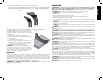
Mitering (Fig. 40) Featherboard Construction (Fig. 41, 42) Featherboards are used to keep the work in contact with the fence and table, and help prevent kickbacks. Dimensions for making a typical featherboard are shown in Figure 41. Make the featherboard from a straight piece of wood that is free of knots and cracks. Clamp the featherboard to the fence and table so that the leading edge of the featherboard will support the workpiece until the cut is complete (Fig. 42).
English Dust Collection (Fig. 43) FIG. 45 FIG. 43 This table saw is equipped with a dustshroud YY and dust collection port. For best results, connect a vacuum to the port at the rear of the saw and on the guard using a Y-connector. The Y connector is available as an accessory at additional cost. Refer to Accessories. NOTICE: Care should be taken to position hoses to not interfere with cutting operation. After extended use, the saw’s dust collection XX system may become clogged.
9. To store fence (K), snap work support in stored position. Remove fence from rails. Reattach fence upside down on left side of saw. Refer to Figure 46. DO NOT hook locator pins on left side fence locator screws. These screws will align with clearance pocket on fence as shown. Pivot fence lock latches to secure.
Push Stick Pattern Modèle de poussoir Patrón de la vara de empuje Adjust length of push stick so hand will clear blade guard and rip fence. Régler la longueur du poussoir de sorte que la main sera dégagée du protège-lame et du guide longitudinal. Ajuste el largo de las varas de empuje para que la mano no obstruya el protector de la hoja y la guía de corte longitudinal. CAUTION: Make push stick from plywood or softwood equal to or less than the width of the material to be cut.