If you have questions or comments, contact us. Pour toute question ou tout commentaire, nous contacter. Si tiene dudas o comentarios, contáctenos. 1-800-4-DEWALT • www.dewalt.com INSTRUCTION MANUAL GUIDE D’UTILISATION MANUAL DE INSTRUCCIONES INSTRUCTIVO DE OPERACIÓN, CENTROS DE SERVICIO Y PÓLIZA DE GARANTÍA. ADVERTENCIA: LÉASE ESTE INSTRUCTIVO ANTES DE USAR EL PRODUCTO.
BEFORE OPERATING THIS TOOL, CAREFULLY READ AND UNDERSTAND ALL INSTRUCTIONS IN THE IMPORTANT SAFETY INSTRUCTIONS SECTION. Definitions: Safety Guidelines The definitions below describe the level of severity for each signal word. Please read the manual and pay attention to these symbols. DANGER: Indicates an imminently hazardous situation which, if not avoided, will result in death or serious injury.
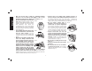
English • Connect tool to air supply before loading fasteners, to prevent a fastener from being fired during connection. The tool driving mechanism may cycle when tool is connected to the air supply. Do not load fasteners with trigger or contact trip depressed, to prevent unintentional firing of a fastener. • Do not remove, tamper with, or FIG. H otherwise cause the tool, trigger, or contact trip to become inoperable. Do not tape or tie trigger or contact trip in the on position.
3 English • Always operate the tool in a clean, FIG. N lighted area. Be sure the work surface is clear of any debris and be careful not to lose footing when working in elevated environments such as rooftops. • Do not drive fasteners near edge of material. The workpiece may split causing the fastener to ricochet, injuring you or a co-worker. Be aware that the nail may follow the grain of the wood (shiner), causing it to protrude unexpectedly from the side of the work material.
English FIG. T BUMP/CONTACT ACTION TRIGGER • When using the contact action trigger, be careful of unintentional double fires resulting from tool recoil. Unwanted fasteners may be driven if the contact trip is allowed to accidentally re-contact the work surface. (Fig. T) TO AVOID DOUBLE FIRES: • Do not engage the tool against the work surface with a strong force. • Allow the tool to recoil fully after each actuation. • Use sequential action trigger.
Tool Specifications MODEL DWFP72155 DESCRIPTION 15 GA "DA" Style Angled Finish Nailer ENGINE TYPE Oil-Free OPERATION PRESSURE 70–120 psi (4.9 – 8.43 kg/cm2) RANGE MAXIMUM OPERATION 120 psi (8.43 kg/cm2) PRESSURE AIR CONSUMPTION AT A RATE OF 60 FASTENERS 1.8 cfm @ 80 psi (5.6 kg/cm2) PER MINUTE * FASTENER TYPE DA Style FASTENER GAUGE 15 Gauge FASTENER RANGE 1-1/4"–2-1/2" (31 mm – 63 mm) MAGAZINE CAPACITY Up to 100 Nails LENGTH 12.8" (325 mm) WIDTH 3.8" (97 mm) HEIGHT 12.1" (307 mm) WEIGHT 4.22 lbs (1.
English COMPONENTS (FIG.1) OPERATION Preparing the Tool G. Pusher H. Swivel air inlet I. Rear exhaust J. Adjustable belt hook K. Depth adjustment wheel L. Pencil sharpener A. Trigger B. Trigger mode selector C. Jam clearing latch D. Contact trip E. No-mar pad F. Magazine FIG. 1 J WARNING: Read the section titled Important Safety Instructions at the beginning of this manual. Always wear eye and ear protection when operating this tool. Keep the nailer pointed away from yourself and others.
Mode Selection CONTACT TRIP ACTION Bump/contact action is intended for rapid nailing on flat, stationary surfaces. When using bump action, two methods are available: place actuation and bump actuation. Rotate the trigger mode selector (B) FIG. 3 counterclockwise to the contact action position , as shown in Figure 3. To operate the tool using the PLACE ACTUATION method: WARNING: A fastener will fire each time the trigger is depressed as long as the contact trip remains depressed. 1.
English 2. Depress the trigger. To operate the tool using the BUMP ACTUATION method: 1. Depress the trigger. 2. Push the contact trip against the work surface. As long as the trigger is depressed, the tool will fire a fastener every time the contact trip is depressed. This allows the user to drive multiple fasteners in sequence. WARNING: Do not keep trigger depressed when tool is not in use. Keep the contact trip lock-off engaged in the locked position when the tool is not in use. THE TOOL MUST NOT CYCLE.
Using The Integrated Pencil Sharpener (Fig. 6) A standard pencil sharpener is integrated into the magazine for the operator’s convenience. To sharpen a pencil, insert any standard pencil into the hole and rotate the pencil to the right (clockwise) to sharpen. FIG. 6 FIG. 5 Integrated Air Blower (Fig. 7) WARNING: NEVER blow debris toward yourself to others in the work area. The integrated air blower helps clean debris while working. Press the integrated air blower button.
English 16" (406 mm) On Center Gauge (Fig. 8) 3. Lower air pressure to 80 psi or less. 4. Actuate the tool 5 or 6 times into scrap lumber to lubricate o-rings. 5. Turn pressure up to operating level (not to exceed 120 psi) and use tool as normal. 16" (406 mm) on center gauge helps to indicate stud location. 1. Pull up the on center gauge to rotate to the opposite side. 2. Press on the on center gauge to snap into the magazine. 3. 16" (406 mm) is measured from nose to the tip of O.C.
Cleaning FIG. 9 Lubrication Daily Maintenance Chart ACTION WHY HOW ACTION WHY HOW ACTION WHY HOW CAUTION: NEVER spray or in any other way apply lubricants or cleaning solvents inside the tool. This can seriously affect the life and performance of the tool. DEWALT tools are properly lubricated at the factory and are ready for use. However, it is recommended that, once a year, you take or send the tool to a certified service center for a thorough cleaning and inspection.
English Accessories 433-9258). This warranty does not apply to accessories or damage caused where repairs have been made or attempted by others. This warranty gives you specific legal rights and you may have other rights which vary in certain states or provinces. WARNING: Since accessories, other than those offered by DEWALT, have not been tested with this product, use of such accessories with this tool could be hazardous.
English TROUBLESHOOTING GUIDE MANY COMMON PROBLEMS CAN BE SOLVED EASILY BY UTILIZING THE CHART BELOW. FOR MORE SERIOUS OR PERSISTENT PROBLEMS, CONTACT A DEWALT SERVICE CENTER OR CALL 1-(800)-4-DEWALT. WARNING: To reduce the risk of serious personal injury, remove fasteners from magazine before making any adjustments or servicing this tool.
TROUBLESHOOTING GUIDE English MANY COMMON PROBLEMS CAN BE SOLVED EASILY BY UTILIZING THE CHART BELOW. FOR MORE SERIOUS OR PERSISTENT PROBLEMS, CONTACT A DEWALT SERVICE CENTER OR CALL 1-(800)-4-DEWALT. WARNING: To reduce the risk of serious personal injury, remove fasteners from magazine before making any adjustments or servicing this tool.
TROUBLESHOOTING GUIDE MANY COMMON PROBLEMS CAN BE SOLVED EASILY BY UTILIZING THE CHART BELOW. FOR MORE SERIOUS OR PERSISTENT PROBLEMS, CONTACT A DEWALT SERVICE CENTER OR CALL 1-(800)-4-DEWALT. 15 English WARNING: To reduce the risk of serious personal injury, remove fasteners from magazine before making any adjustments or servicing this tool.
Directives de sécurité importantes AVANT DE FAIRE FONCTIONNER CET OUTIL, LIRE ATTENTIVEMENT ET COMPRENDRE TOUTES LES DIRECTIVES DE LA SECTION “CONSIGNES DE SÉCURITÉ IMPORTANTES” AVERTISSEMENT: ne pas utiliser cet appareil avant d’avoir lu le mode d’emploi ainsi que l’intégralité des directives de sécurité, d’utilisation et d’entretien. FIG.
• Débrancher l’outil de la source FIG. E d’alimentation en air lorsqu’il n’est pas utilisé. Toujours débrancher l’outil de la source d’alimentation en air et retirer les attaches qui se trouvent dans le magasin avant de quitter la zone de travail ou de remettre l’outil à un autre opérateur. Ne pas transporter l’outil vers une autre zone de travail FIG. F qui comprend des échafaudages, des marches, des échelles etc., avec la source d’alimentation en air raccordée.
Français • • • • • • Enlever le doigt de la détente lorsque vous ne clouez pas. Ne jamais transporter l’outil avec le doigt sur la détente. Cette pratique pourrait se solder par une décharge intempestive. Utiliser le bouton de verrouillage de la détente pour empêcher une décharge intempestive • Ne pas tendre le bras trop loin. Il faut FIG. K demeurer bien campé sur ses pieds et en équilibre en tout temps. Une perte d’équilibre risquerait d’entraîner une blessure corporelle. (fig.
19 Français sa gamme de fonctionnement, les FIG. Q clous peuvent passer complètement à travers un matériau mince ou très souple. S’assurer que la pression dans le compresseur est réglée de sorte que les clous sont fixés dans le matériau et non poussés entièrement dans celui-ci. (Fig. P) • Garder les mains et les parties du corps éloignées de la zone de travail immédiate. Au besoin, maintenir la pièce FIG.
Français • RÉGLAGE DE PROFONDEURŸ: Afin de réduire les risques de blessure grave causée par le démarrage accidentel de l’outil lorsqu’on tente de régler la profondeur, on doit TOUJOURS : • débrancher l’alimentation d’air. • éviter tout contact avec la gâchette durant l’ajustement • Ne pas enfoncer de clous à l’aveugle FIG. U dans les murs, les planchers ou autres zones de travail.
MODÈLE DWFP72155 TYPE DE FIXATION DA CALIBRE DES FIXATIONS 15 PLAGE DE DIMENSION DES 31 mm – 63 mm FIXATIONS (1 1/4 po – 2 1/2 po) CAPACITÉ DU CHARGEUR Jusqu’à 100 clous LONGUEUR 325 mm (12,8 po) LARGEUR 97 mm (3,8 po) HAUTEUR 307 mm (12,1 po) POIDS 1,9 kg (4,22 lb) *Le modèle DWFP72155 a besoin de 51 litres par minute (1,8 pi³/min) d’air libre à une pression de 5,6 kg/cm2 (80 psi) pour fonctionner à un taux de 60 fixations par minute.
COMPOSANTS (FIG. 1) A. Gâchette B. Sélecteur de mode de la gâchette C. Loquet de dégagement D. Déclenchement par contact E. Tampon antimarque F. Chargeur FIG. 1 Français FONCTIONNEMENT Préparation de l’outil G. Poussoir H. Raccord d’entrée d’air rotatif I. Échappement arrière J. Crochet pour ceinture réglable K. Molette de réglage de profondeur L. Taille-crayon J AVERTISSEMENT: Lire la section intitulée Directives de sécurité importantes début ce manuel.
Ainsi, une fixation est libérée à chaque contact avec la surface. Cette méthode favorise le positionnement rapide des fixations dans de nombreux travaux. Un recul se produit sur tous les outils pneumatiques lors de la libération de fixations. Il peut arriver que le rebond qui s’ensuit libère le déclencheur. En cas de contact involontaire avec la surface de travail alors que la gâchette est toujours actionnée (doigt sur la gâchette enfoncée), une deuxième fixation sera libérée.
Français Vérification du fonctionnement de l’outil (fig. 1) DÉCLENCHEMENT PAR CONTACT Le déclenchement par choc/contact est conçu pour un clouage rapide sur des surfaces planes et fixes. Deux méthodes sont proposées pour le FIG. 3 déclenchement par choc : l’actionnement par positionnement et l’actionnement par choc. Tourner le sélecteur de mode de la gâchette (B) dans le sens antihoraire jusqu’à la position d’actionnement par contact , comme illustré à la figure 3.
D. Sans toucher la gâchette, appuyer le déclencheur par contact contre la surface de travail, puis appuyer sur la gâchette. L’OUTIL DOIT SE DÉCLENCHER. 1. Tirer le poussoir vers l’arrière jusqu’à ce qu’il se verrouille à l’extrémité du chargeur. 2. Charger les clous dans la fente située à l’arrière du chargeur, jusqu’après le ressort de retenue. 3. Appuyer sur le bouton pour relâcher le poussoir jusqu’à ce qu’il exerce une poussée sur les clous. 4.
Utilisation du taille-crayon intégré (fig. 6) Calibre d’angle de 406 mm (16 po) (fig. 8) Un taille-crayon standard est intégré au chargeur pour faciliter le travail de l’utilisateur. Pour tailler un crayon standard, l’insérer dans le trou puis le faire tourner dans le sens horaire. ole and rotate the pencil to the right (clockwise) to sharpen. Le calibre d’angle de 406 mm (16 po) indique l’emplacement des goujons. 1. Tirer le calibre d’angle vers le haut pour le faire pivoter de l’autre côté. 2.
4. Retirer la fixation coincée. Il peut être nécessaire d’utiliser une pince pour décoincer la fixation. 5. Fermer le verrou de la porte de dégagement du nez. 6. Tirer le poussoir jusque derrière les rames de clous. 7. Vérifier le fonctionnement de l’outil. REMARQUE : Si les fixations continuent de se coincer fréquemment dans l’embout, faites réparer votre outil par un centre de service DEWALT autorisé. 1. S’assurer que les réservoirs du compresseur ont été purgés adéquatement avant l’utilisation.
COMMENT ACTION POURQUOI COMMENT une fois par année dans un centre de service qualifié afin qu’ils puissent être complètement nettoyés et inspectés. Nettoyer à l’air comprimé.
Registre en ligne SERVICE D’ENTRETIEN GRATUIT DE 1 AN DEWALT entretiendra l’outil et remplacera les pièces usées par une utilisation normale et ce, gratuitement, à tout moment pendant la première année à compter de la date d’achat. L’usure de pièces comme les joints toriques ou les mécanismes de lames n’est pas couverte.
Français GUIDE DE DÉPANNAGE IL EST POSSIBLE DE RÉSOUDRE FACILEMENT LES PROBLÈMES LES PLUS COMMUNS À L’AIDE DU TABLEAU CI-DESSOUS. POUR DES PROBLÈMES PLUS GRAVES OU DES PROBLÈMES QUI PERSISTENT, COMMUNIQUER AVEC UN CENTRE DE RÉPARATION DEWALT OU COMPOSER LE 1 800 4-DEWALT. AVERTISSEMENT : pour réduire les risques de blessures graves, retirer les fixations du chargeur avant de régler, entretenir ou réparer l’outil.
GUIDE DE DÉPANNAGE 31 Français IL EST POSSIBLE DE RÉSOUDRE FACILEMENT LES PROBLÈMES LES PLUS COMMUNS À L’AIDE DU TABLEAU CI-DESSOUS. POUR DES PROBLÈMES PLUS GRAVES OU DES PROBLÈMES QUI PERSISTENT, COMMUNIQUER AVEC UN CENTRE DE RÉPARATION DEWALT OU COMPOSER LE 1 800 4-DEWALT. AVERTISSEMENT : pour réduire les risques de blessures graves, retirer les fixations du chargeur avant de régler, entretenir ou réparer l’outil.
Français GUIDE DE DÉPANNAGE IL EST POSSIBLE DE RÉSOUDRE FACILEMENT LES PROBLÈMES LES PLUS COMMUNS À L’AIDE DU TABLEAU CI-DESSOUS. POUR DES PROBLÈMES PLUS GRAVES OU DES PROBLÈMES QUI PERSISTENT, COMMUNIQUER AVEC UN CENTRE DE RÉPARATION DEWALT OU COMPOSER LE 1 800 4-DEWALT. AVERTISSEMENT : pour réduire les risques de blessures graves, retirer les fixations du chargeur avant de régler, entretenir ou réparer l’outil.
ANTES DE OPERAR ESTA HERRAMIENTA LEA CON DETENIMIENTO LAS INSTRUCCIONES DEL APARTADO “INSTRUCCIONES IMPORTANTES DE SEGURIDAD”. Definiciones: Normas de seguridad Las siguientes definiciones describen el nivel de gravedad de cada palabra de señal. Lea el manual y preste atención a estos símbolos. PELIGRO: Indica una situación de peligro inminente que, si no se evita, provocará la muerte o lesiones graves.
Español • Utilice conexiones que alivien toda la presión de la herramienta cuando se desconecte de la toma de corriente. Utilice conectores de mangueras que bloqueen el suministro de aire del compresor cuando la herramienta se desconecte. (Fig. F) • Desconecte la herramienta del suministro de aire cuando no se vaya a usar. Siempre desconecte la herramienta del suministro de aire y retire los clavos del cargador antes de dejar la zona de trabajo o de pasar la herramienta a otro operador.
35 Español • No ponga en peligro su estabilidad. FIG. K Manténgase siempre bien apoyado y equilibrado. La pérdida del equilibrio podría provocar una lesión personal. (Fig. K) • La manguera debe estar libre de obstrucciones o enganches. Las mangueras enredadas o enmarañadas pueden provocar una pérdida de equilibrio o una falta de apoyo. FIG. L • Use la herramienta sólo para lo que fue diseñada.
Español • No intente insertar grapas cerca del FIG. N borde del material. La pieza de trabajo podría quebrarse y hacer que la grapa rebotase, lesionándolo a usted o a un compañero. Observe también que la grapa puede insertarse siguiendo la dirección de la veta de la madera, haciendo que sobresalga inesperadamente de un lado del material de trabajo. Inserte el clavo perpendicular al grano de la madera para reducir el riesgo de lesiones. (Fig.
GATILLO SECUENCIAL • Cuando utilice el gatillo secuencial no opere la herramienta a menos que esté firmemente colocada contra la pieza. • AJUSTE DE PROFUNDIDAD: Para reducir el riesgo de lesiones graves causados por la activación accidental al tratar de ajustar la profundidad. SIEMPRE se debe: • Desconecte el suministro de aire 37 Español • Evitar contacto con el gatillo durante los ajustes • No clave indiscriminadamente en FIG. U paredes, suelos u otras superficies de trabajo.
ADVERTENCIA: USE SIEMPRE LENTES DE SEGURIDAD. Los anteojos de uso diario NO son lentes de seguridad. Utilice también máscaras faciales o para polvo si la operación produce polvillo. UTILICE SIEMPRE EQUIPOS DE SEGURIDAD CERTIFICADOS: • Protección para los ojos ANSI Z87.1(CAN/CSA Z94.3), • protección auditiva ANSI S12.6 (S3.19), • Protección respiratoria según las normas NIOSH/OSHA/MSHA.
COMPONENTES (FIG. 1) A. Gatillo B. Selector del modo de gatillo C. Seguro de liberación de obstrucciones D. Interruptor de contacto E. Almohadilla contra daños F. Cargador FUNCIONAMIENTO Preparación de la herramienta G. Impulsor H. Entrada oscilante de aire I. Escape trasero J. Gancho ajustable para el cinturón K. Rueda de ajuste de profundidad L. Sacapuntas FIG.
superficie de trabajo para accionar el mecanismo de activación mientras mantiene el gatillo presionado, accionando así un remache cada vez que toca la superficie de trabajo. Esto permitirá una colocación rápida de los remaches en numerosos trabajos. Todas las herramientas neumáticas están sujetas al rebote al colocar remaches.
ADVERTENCIA: El interruptor de contacto debe presionarse, seguido de una presión en el gatillo para cada remache, seguido de la liberación tanto del interruptor de contacto como del gatillo después de cada remache. ADVERTENCIA: No mantenga el gatillo presionado cuando la herramienta no está en uso. Mantenga el bloqueo del interruptor de contacto en la posición de bloqueo cuando la herramienta no está en uso.
TIRAR DEL IMPULSOR PARA BLOQUEAR Y CARGAR (Fig. 5) LA HERRAMIENTA NO DEBE ACCIONARSE. C. Con la herramienta sin apoyar sobre la superficie de trabajo, presione el gatillo. Presione el interruptor de contacto contra la superficie de trabajo. LA HERRAMIENTA DEBE ACCIONARSE. D. Sin tocar el gatillo, presione el interruptor de contacto contra la superficie de trabajo, luego presione el gatillo. LA HERRAMIENTA DEBE ACCIONARSE. ATENCIÓN: Mantenga los dedos alejados del impulsor para prevenir lesiones. 1.
Gancho de cinturón (Fig. 1) FIG. 7 El gancho integrado para cinturón (J) puede girarse a cualquier lado de la herramienta para ajustarse a usuarios diestros o zurdos. AVISO: El gancho de cinturón no puede quitarse. Uso del sacapuntas integrado (Fig. 6) Para la comodidad del operador, el gancho para el cinturón tiene integrado un sacapuntas estándar. Para afilar un lápiz, inserte cualquier lápiz estándar en el orificio y gírelo hacia la derecha (en sentido horario).
Español Funcionamiento en climas fríos Liberar un remache obstruido (Fig. 1, 9) ADVERTENCIA: Lea el apartado titulado Instrucciones importantes de seguridad a principios de este manual. Lleve siempre protección ocular y auditiva cuando trabaje con esta herramienta. No apunte con la clavadora a ninguna persona ni a usted mismo. Para una operación segura lleve a cabo los procedimientos y comprobaciones siguientes antes de cada utilización de la clavadora.
Cuadro de mantenimiento diario ACCIÓN MOTIVO MÉTODO ACCIÓN MOTIVO MÉTODO ACCIÓN MOTIVO MÉTODO agua y jabón neutro. Nunca permita que penetre líquido dentro de la herramienta ni sumerja ninguna de las piezas en un líquido. Drene los tanques del compresor y las mangueras diariamente Evita la acumulación de humedad en el compresor y en la clavadora Abra los grifos de descompresión u otras válvulas de drenaje en los tanques del compresor.
garantía le proporciona derechos legales específicos y usted puede tener otros derechos que varían en ciertos estados o provincias. Además de esta garantía, las herramientas DEWALT están cubiertas por nuestro: Los accesorios que se recomiendan para utilizar con la herramienta están disponibles a un costo adicional en su distribuidor local o en un centro de mantenimiento autorizado. Si necesita ayuda para localizar algún accesorio, póngase en contacto con DEWALT Industrial Tool Co.
GUÍA DE SOLUCIÓN DE PROBLEMAS 47 Español CON LA TABLA SIGUIENTE, PODRÁ SOLUCIONAR MUCHOS PROBLEMAS COMUNES CON FACILIDAD. PARA PROBLEMAS PERSISTENTES O MÁS GRAVES, PÓNGASE EN CONTACTO CON EL CENTRO DE MANTENIMIENTO DEWALT O LLAME AL 1-(800)-4-DEWALT.
Español GUÍA DE SOLUCIÓN DE PROBLEMAS CON LA TABLA SIGUIENTE, PODRÁ SOLUCIONAR MUCHOS PROBLEMAS COMUNES CON FACILIDAD. PARA PROBLEMAS PERSISTENTES O MÁS GRAVES, PÓNGASE EN CONTACTO CON EL CENTRO DE MANTENIMIENTO DEWALT O LLAME AL 1-(800)-4-DEWALT.
GUÍA DE SOLUCIÓN DE PROBLEMAS CON LA TABLA SIGUIENTE, PODRÁ SOLUCIONAR MUCHOS PROBLEMAS COMUNES CON FACILIDAD. PARA PROBLEMAS PERSISTENTES O MÁS GRAVES, PÓNGASE EN CONTACTO CON EL CENTRO DE MANTENIMIENTO DEWALT O LLAME AL 1-(800)-4-DEWALT.
Industrial 23+ CFM Industriel 23 pieds cubes par minute et + Industrial 23+ CFM 8 HP Gas 14 - 16 CFM 8 CH Essence 14 à 16 pieds cubes par minute 8 CV Gas 14 -16 CFM 5.5 HP Gas/2 HP Elec. 8 - 9 CFM 5.5 HP Essence/ 2 CH Élec. 8 à 9 pieds cubes par minute 5.5 CV Gas/ 2 CV Elec. 8 -9 CFM Portable Handcarry 3.2 - 4 CFM Portable à la main 3,2 à 4 pieds cubes par minute Transportable 3.