IF YOU SHOULD EXPERIENCE A PROBLEM WITH YOUR DEWALT PURCHASE, Before returning this product call 1-800-4-DEWALT CALL 1-800-4-DEWALT IN MOST CASES, A DEWALT REPRESENTATIVE CAN RESOLVE YOUR PROBLEM OVER THE PHONE. IF YOU HAVE A SUGGESTION OR COMMENT, GIVE US A CALL. YOUR FEEDBACK IS VITAL TO THE SUCCESS OF DEWALT’S QUALITY IMPROVEMENT PROGRAM. Questions? Visit us at www.dewalt.com Des questions ? Rendez nous visite à www.dewalt.com ¿Tiene preguntas? Visítenos en www.dewalt.
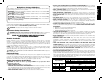
The definitions below describe the level of severity for each signal word. Please read the manual and pay attention to these symbols. DANGER: Indicates an imminently hazardous situation which, if not avoided, will result in death or serious injury. WARNING: Indicates a potentially hazardous situation which, if not avoided, could result in death or serious injury. CAUTION: Indicates a potentially hazardous situation which, if not avoided, may result in minor or moderate injury.
English • NEVER CUT FERROUS METALS (those with any iron or steel content) or masonry. Either of these can cause the carbide tips to fly off the blade at high speeds causing serious injury. • DO NOT USE ABRASIVE WHEELS. The excessive heat and abrasive particles generated by them may damage the saw and cause personal injury. • NEVER HAVE ANY PART OF YOUR BODY IN LINE WITH THE PATH OF THE SAW BLADE. Personal injury will occur. • NEVER APPLY BLADE LUBRICANT TO A RUNNING BLADE.
ON GUARD: DANGER–KEEP AWAY FROM BLADE. ON UPPER GUARD: PROPERLY SECURE BRACKET WITH BOTH SCREWS BEFORE USE. ON TABLE: (2 PLACES) WARNING: FOR YOUR OWN SAFETY, READ INSTRUCTION MANUAL BEFORE OPERATING MITER SAW. KEEP HANDS OUT OF PATH OF SAW BLADE. DO NOT OPERATE SAW WITHOUT GUARDS IN PLACE. CHECK LOWER GUARD FOR PROPER CLOSING BEFORE EACH USE. ALWAYS TIGHTEN ADJUSTMENT KNOBS BEFORE USE. DO NOT PERFORM ANY OPERATION FREEHAND. NEVER REACH IN BACK OF SAW BLADE. NEVER CROSS ARMS IN FRONT OF BLADE.
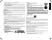
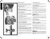
English FIG. 1 BLADE DESCRIPTIONS APPLICATION DIAMETER TEETH Construction Saw Blades (thin kerf with anti-stick rim) General Purpose 12" (305 mm) 40 Fine Crosscuts 12" (305 mm) 60 Woodworking Saw Blades (provide smooth, clean cuts) Fine crosscuts 12" (305 mm) 80 Non-ferrous metals 12" (305 mm) 96 NOTE: For cutting non-ferrous metals, use only saw blades with TCG (Triple Chip Grind) teeth designed for this purpose.
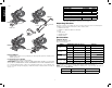
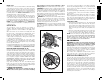
• Do not cut ferrous metal (containing iron or steel) or masonry or fiber cement product with this miter saw. DRIVE Removing the Blade (Fig. 3) 15 amp motor Cut helical gears Roller bearings Carbide blade 1. Unplug the saw. 2. Raise the arm to the upper position and raise the lower guard (A) as far as possible. 3. Loosen, but do not remove guard bracket screw (B) until the bracket can be raised far enough to access the blade screw (E).
MITER CONTROL (FIG. 5) The miter lock handle and miter latch button allow you to miter your saw to 60° right and 50° left. To miter the saw, lift the miter lock handle, push the miter latch button and set the miter angle desired on the miter scale. Push down on the miter lock handle to lock the miter angle. English FIG. 3 TRIGGER SWITCH (FIG. 4) The trigger switch turns your saw on and off. A hole is provided in the trigger for insertion of a padlock to secure the saw. A B MITER LATCH OVERRIDE (FIG.
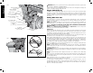
FIG. 4 LIFTING HANDLE RAIL LOCK KNOB OPERATING HANDLE TRIGGER SWITCH RAIL SET SCREW ADJUSTMENT DEPTH ADJUSTMENT SCREW LOWER GUARD MOTOR ENDCAP BELT COVER WING NUT DEPTH STOP RAILS KERF PLATE BEVEL SCALE LOCK DOWN PIN 0° BEVEL STOP FENCE ADJUSTMENT KNOB MITER LATCH BUTTON (one each side) BLADE WRENCH FENCE ADJUSTMENT KNOB (ONE EACH SIDE) DUST DUCT INLET TABLE HAND INDENTATION MITER LATCH OVERRIDE BASE FIG.
English FIG. 6 WARNING: Always use eye protection. All users and bystanders must wear eye protection that conforms to ANSI Z87.1 (CAN/CSA Z94.3). Plug the saw into any household 60 Hz power source. Refer to the nameplate for voltage. Be sure the cord will not interfere with your work. BEVEL POINTER SCREW (one each side) BEVEL POINTER (one each side) Trigger Switch (Fig. 4) To turn the saw on, depress the trigger switch. To turn the tool off, release the switch.
QUALITY OF CUT The smoothness of any cut depends on a number of variables. Things like material being cut, blade type, blade sharpness and rate of cut all contribute to the quality of the cut. When smoothest cuts are desired for molding and other precision work, a sharp (60 tooth carbide) blade and a slower, even cutting rate will produce the desired results. Ensure that the material does not move or creep while cutting; clamp it securely in place.
English right, if the bevel pointer does not indicate exactly 22.5°, turn the crown adjustment screw contacting the pawl with a 7/16" (10 mm) wrench until the bevel pointer indicates exactly 22.5°. MITER POINTER ADJUSTMENT (FIG. 5) Unlock the miter lock handle to move the miter arm to the zero position. With the miter lock handle unlocked, allow the miter latch to snap into place as you rotate the miter arm to zero. Observe the miter pointer and miter scale shown in Figure 5.
counterclockwise one turn. To ensure the miter lock is functioning properly, re-lock the miter lock to a non-detented measurement on the miter scale – for example, 34º – and make sure the table will not rotate. Tighten lock nut. – EXAMPLES – WARNING: To reduce the risk of injury, turn unit off and disconnect it from power source before installing and removing accessories, before adjusting or when making repairs. An accidental start-up can cause injury. ALWAYS SUPPORT LONG PIECES.
English Left side Right side INSIDE CORNER OUTSIDE CORNER Miter left 45° Save left side of cut Miter right 45° Save left side of cut Miter right 45° Save right side of cut Miter left 45° Save right side of cut Left side Right side Material up to 6.75" (171 mm) can be cut as described above. FIG. 16 INSIDE CORNER OUTSIDE CORNER Bevel left 33.9° Miter table set at right 31.62° Save left end of cut Bevel right 33.9° Miter table set at left 31.62° Save left end of cut Bevel right 33.
Special Cuts NEVER MAKE ANY CUT UNLESS THE MATERIAL IS SECURED ON THE TABLE AND AGAINST THE FENCE. FIG. 20 FIG. 19 English ALUMINUM CUTTING (FIG. 19, 20) ALWAYS USE THE APPROPRIATE SAW BLADE MADE ESPECIALLY FOR CUTTING ALUMINUM. These are available at your local DEWALT retailer or DEWALT service center. Certain workpieces, due to their size, shape or surface finish, may require the use of a clamp or fixture to prevent movement during the cut.
English NOTICE: Overtightening the belt will cause premature motor failure. 3. Mount the 14.5" x 26" (368 x 660 mm) platform to the saw using four 3" (76.2 mm) long wood screws through the holes in the base fence (Fig. 24). Four screws must be used to properly secure the material. When the special set-up is used, the platform will be cut into two pieces. Ensure the screws are tightened properly, otherwise material could loosen and cause injury.
• FOR YOUR SAFETY: Registering your product will allow us to contact you in the unlikely event a safety notification is required under the Federal Consumer Safety Act. Register online at www.dewalt.com/register. Troubleshooting Guide BE SURE TO FOLLOW SAFETY RULES AND INSTRUCTIONS DEWALT will repair, without charge, any defects due to faulty materials or workmanship for three years from the date of purchase. This warranty does not cover part failure due to normal wear or tool abuse.
TABLE 1: COMPOUND MITER CUT English (POSITION WOOD WITH BROAD FLAT SIDE ON THE TABLE AND THE NARROW EDGE AGAINST THE FENCE) X BO 16 ANGLE OF SIDE OF BOX (ANGLE A) X BO X BO SET THIS MITER ANGLE ON SAW RE UA SQ D DE SI 6- D DE SI 8SET THIS BEVEL ANGLE ON SAW